Entity Relationship Diagram Symbols

This AD diagram example was redesigned from the picture "Asymmetric
encryption" from the book "Active Directory for Dummies".
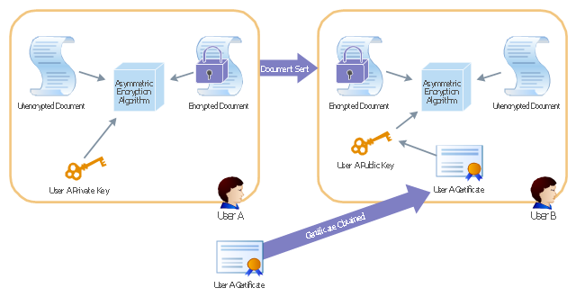
"Asymmetric Encryption:
This scenario uses a public and private key pair that is associated with each other. With this type of encryption, one of the keys is used to encrypt the data in such a way that only the corresponding second key is capable of decrypting the information. ...
In asymmetric encryption, two different keys are involved in the process: one for encrypting the document and a different but related key for decrypting the document. The two keys are generated at the same time so that if a document is encrypted with one of the keys, only the second related key can decrypt the document. ... Typically, these keys are referred to as a private key and a public key. A private key is one that is generated for a particular user and is never shared with any other user or computer. A public key is typically one of the pieces of data that’s stored in a PKI certificate. Although this type of encryption creates a very secure way of sharing data, an added benefit is you knowing that a piece of data decrypted by using a particular user’s public key must have come from that user because no other user would have the private key the document was encrypted with."
[Steve Clines and Marcia Loughry, Active Directory® For Dummies®, 2nd Edition. 2008]
The Active Directory diagram example "Asymmetric encryption" was created using the ConceptDraw PRO diagramming and vector drawing software extended with the Active Directory Diagrams solution from the Computer and Networks area of ConceptDraw Solution Park.
encryption" from the book "Active Directory for Dummies".
"Asymmetric Encryption:
This scenario uses a public and private key pair that is associated with each other. With this type of encryption, one of the keys is used to encrypt the data in such a way that only the corresponding second key is capable of decrypting the information. ...
In asymmetric encryption, two different keys are involved in the process: one for encrypting the document and a different but related key for decrypting the document. The two keys are generated at the same time so that if a document is encrypted with one of the keys, only the second related key can decrypt the document. ... Typically, these keys are referred to as a private key and a public key. A private key is one that is generated for a particular user and is never shared with any other user or computer. A public key is typically one of the pieces of data that’s stored in a PKI certificate. Although this type of encryption creates a very secure way of sharing data, an added benefit is you knowing that a piece of data decrypted by using a particular user’s public key must have come from that user because no other user would have the private key the document was encrypted with."
[Steve Clines and Marcia Loughry, Active Directory® For Dummies®, 2nd Edition. 2008]
The Active Directory diagram example "Asymmetric encryption" was created using the ConceptDraw PRO diagramming and vector drawing software extended with the Active Directory Diagrams solution from the Computer and Networks area of ConceptDraw Solution Park.
Active Directory diagram
Basic Flowchart Symbols and Meaning


Flowchart Components

This Azure cloud architecture pattern diagram template was created on the base of figure in the article "Valet Key Pattern" from the Microsoft Developer Network (MSDN) website.
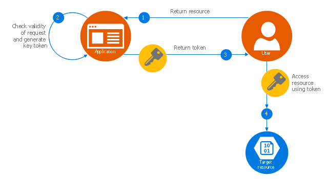
"Valet Key Pattern.
Use a token or key that provides clients with restricted direct access to a specific resource or service in order to offload data transfer operations from the application code. This pattern is particularly useful in applications that use cloud-hosted storage systems or queues, and can minimize cost and maximize scalability and performance. ...
Client programs and web browsers often need to read and write files or data streams to and from an application’s storage. ...
Data stores have the capability to handle upload and download of data directly, without requiring the application to perform any processing to move this data, but this typically requires the client to have access to the security credentials for the store.
... applications must be able to securely control access to data in a granular way, but still reduce the load on the server by setting up this connection and then allowing the client to communicate directly with the data store to perform the required read or write operations. ...
To resolve the problem of controlling access to a data store where the store itself cannot manage authentication and authorization of clients, one typical solution is to restrict access to the data store’s public connection and provide the client with a key or token that the data store itself can validate.
This key or token is usually referred to as a valet key. It provides time-limited access to specific resources and allows only predefined operations such as reading and writing to storage or queues, or uploading and downloading in a web browser. Applications can create and issue valet keys to client devices and web browsers quickly and easily, allowing clients to perform the required operations without requiring the application to directly handle the data transfer. This removes the processing overhead, and the consequent impact on performance and scalability, from the application and the server." [msdn.microsoft.com/ ru-RU/ library/ dn568102.aspx]
The Azure cloud system architecture diagram template "Valet key pattern" for the ConceptDraw PRO diagramming and vector drawing software is included in the Azure Architecture solutin from the Computer and Networks area of ConceptDraw Solution Park.
Cloud computing system architecture diagram template
ConceptDraw PRO ER Diagram Tool

"Chen's notation for entity–relationship modeling uses rectangles to represent entity sets, and diamonds to represent relationships appropriate for first-class objects: they can have attributes and relationships of their own. If an entity set participates in a relationship set, they are connected with a line.
Attributes are drawn as ovals and are connected with a line to exactly one entity or relationship set.
Cardinality constraints are expressed as follows:
- a double line indicates a participation constraint, totality or surjectivity: all entities in the entity set must participate in at least one relationship in the relationship set;
- an arrow from entity set to relationship set indicates a key constraint, i.e. injectivity: each entity of the entity set can participate in at most one relationship in the relationship set;
- a thick line indicates both, i.e. bijectivity: each entity in the entity set is involved in exactly one relationship.
- an underlined name of an attribute indicates that it is a key: two different entities or relationships with this attribute always have different values for this attribute.
Attributes are often omitted as they can clutter up a diagram; other diagram techniques often list entity attributes within the rectangles drawn for entity sets." [Entity–relationship model. Wikipedia]
The vector stencils library ERD, Chen's notation contains 13 symbols for drawing entity-relatinship diagrams using the ConceptDraw PRO diagramming and vector drawing software.
The example "Design elements - ER diagram (Chen notation)" is included in the Entity-Relationship Diagram (ERD) solution from the Software Development area of ConceptDraw Solution Park.
Chen's ERD
.png--diagram-flowchart-example.png)
ERD Symbols and Meanings


Business Process Modeling Notation

ConceptDraw PRO Network Diagram Tool


- How To Represent Foreign Key In Er Diagram
- Er Diagram With Unique Key
- Flowcharts | Shape To Represent Foreign Key In Er Diagram
- Design elements - ER diagram (Chen notation) | Flowcharts | Spatial ...
- Foreign Key Representation In Er Diagram
- Timeline Diagrams | Fishbone Diagrams | Draw Timeline And ...
- Key Attribute Er Diagram
- Identify Key Attributes In An Er Diagram
- Diagram Legend Or Key
- Erd Unique Key Represent