UML Notation

UML Diagram Types List

UML Diagramming Software

UML Diagram Software
About UML

 Rapid UML
Rapid UML solution extends ConceptDraw DIAGRAM software with templates, samples and libraries of vector stencils for quick drawing the UML diagrams using Rapid Draw technology.
HelpDesk
How to Make a UML Diagram

UML Business Process

UML Use Case Diagram. Design Elements


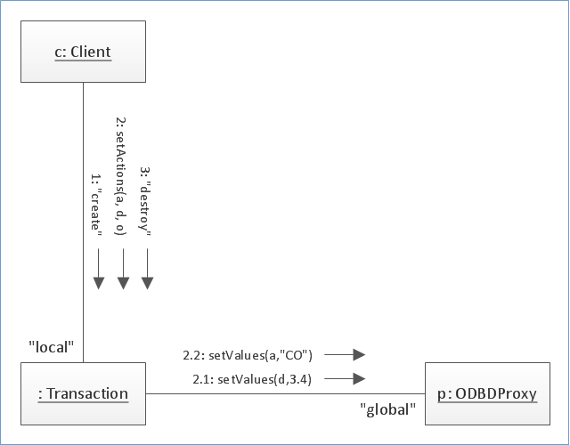
"Communication diagram (called collaboration diagram in UML 1.x) is a kind of UML interaction diagram which shows interactions between objects and/ or parts (represented as lifelines) using sequenced messages in a free-form arrangement.
Communication diagram corresponds (i.e. could be converted to/ from or replaced by) to a simple sequence diagram without structuring mechanisms such as interaction uses and combined fragments. It is also assumed that message overtaking (i.e., the order of the receptions are different from the order of sending of a given set of messages) will not take place or is irrelevant." [uml-diagrams.org/ communication-diagrams.html]
The template "UML communication diagram" for the ConceptDraw PRO diagramming and vector drawing software is included in the Rapid UML solution from the Software Development area of ConceptDraw Solution Park.
www.conceptdraw.com/ solution-park/ software-uml
UML communication diagram
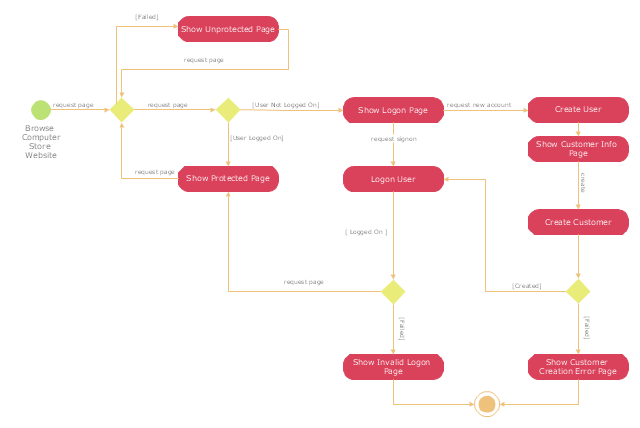
"A registered user is one who uses a program or a website and provides his/ her credentials, effectively proving his/ her identity. ...
Generally speaking, any person can become a registered user by providing some credentials, usually in the form of a username (or email) and password. After that, one can access information and privileges unavailable to non-registered users, usually referred to simply as guests. The action of providing the proper credentials for a website is called logging in, or signing in." [Registered user. Wikipedia]
The UML activity diagram example "User registration" was created using the ConceptDraw PRO diagramming and vector drawing software extended with the Rapid UML solution from the Software Development area of ConceptDraw Solution Park.
UML activity diagram
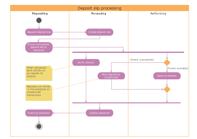
"Credits and deposits.
To add credit to an account by bringing cash to a bank in person, the account holder can fill a small credit slip or deposit slip. The total amount of each note and coin is counted and entered on the slip, along with who it is paid in by and the date. The cash and details are counted and checked by the teller at the bank, if everything is in order the deposit is credited to the account, the credit slip is then kept by the bank and the credit slip booklet is stamped with the date and then returned to the account holder.An account holder uses their passbook to record their history of transactions with their bank." [Passbook. Wikipedia]
The UML activity diagram example "Deposit slip processing" was created using the ConceptDraw PRO diagramming and vector drawing software extended with the Rapid UML solution from the Software Development area of ConceptDraw Solution Park.
UML activity diagram
 Rapid UML
Rapid UML solution extends ConceptDraw DIAGRAM software with templates, samples and libraries of vector stencils for quick drawing the UML diagrams using Rapid Draw technology.
UML Software

UML Class Diagram Constructor

UML Use Case Diagram Example. Registration System

SysML

 Accounting Flowcharts
Accounting Flowcharts solution extends ConceptDraw DIAGRAM software with templates, samples and library of vector stencils for drawing the accounting flow charts.
- UML Notation | Notation &Symbols for ERD | Business Process ...
- UML Deployment Diagram | Diagramming Software for Design UML ...
- Basic Flowchart Symbols | Types of Flowcharts | UML Notation ...
- Types of Flowcharts | UML Notation | Flow Chart Uses Standard ...
- Diagramming Software for Design UML Collaboration Diagrams ...
- Timing diagram | Rapid UML | Rapid UML | Uses Of Timing Diagram
- UML Package Diagram | Diagramming Software for Design UML ...
- UML Diagram Types List | UML Notation | UML Diagrams with ...
- UML Deployment Diagram
- UML Diagram | UML Diagram Types List | UML for Software ...
- UML Class Diagrams. Diagramming Software for Design UML ...
- UML Diagrams with ConceptDraw PRO | UML Deployment Diagram ...
- UML Notation | Business Process Modeling with ConceptDraw ...
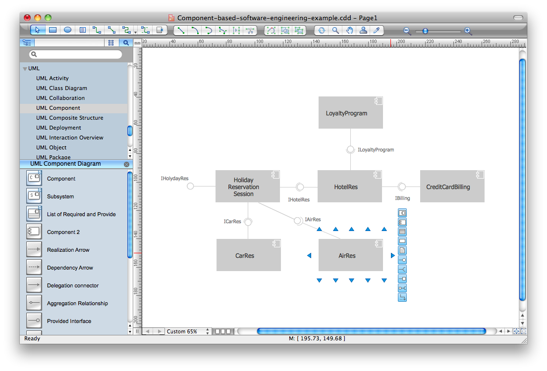
- UML Component Diagram. Design Elements | UML Class Diagram ...
- Project —Task Trees and Dependencies | PM Easy | Diagramming ...
- UML Notation | Design elements - Bearings | UML Class Diagram ...
- UML Notation | UML Diagram Types List | Software and Database ...
- UML Sequence Diagram. Design Elements | UML Interaction ...
- UML Class Diagram Constructor | Chen's ERD of MMORPG | UML ...
- UML Diagram Types List | UML Diagrams with ConceptDraw PRO ...