Products
Solutions
Samples
Contact Us
Buy
Helpdesk
✕
Sign In
Sign In
My ConceptDraw
Profile
Cart 
Activate
My Activated Licenses
Upgrade Information
Download Product
Open Support Ticket
Sign Out
This site uses cookies. By continuing to browse the ConceptDraw site you are agreeing to our Use of Site Cookies.
Helpdesk  >  ConceptDraw DIAGRAM  >    Business-specific Drawings

How to Make a UML Diagram

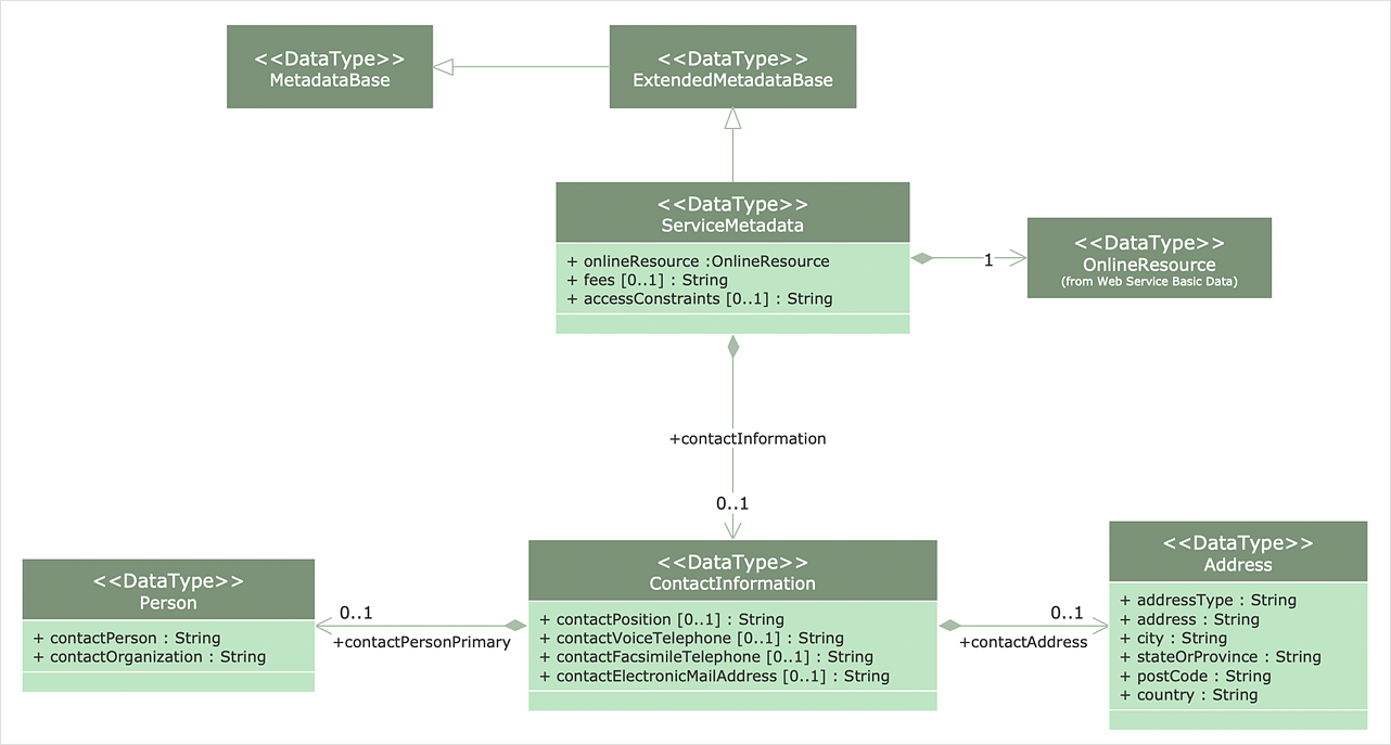
The Unified Modeling Language™(UML) is a standard visual modeling language to document business processes and software architecture. UML uses several types of diagrams including Use Case Diagrams, Class, Package, Component, Composite Structure Diagrams, Deployments, Activities, and Interactions. The accepted standard used when modeling a system is known as the Unified Modeling Language (UML), a generic set of notations that are used when creating UML diagrams. These notations can visually represent requirements, subsystems, logical and physical elements, and structural and behavioral patterns, that are especially relevant to systems built using an object-oriented style. Using UML during the modeling process has a number of benefits — for one, the entire development team can share information and collaborate using a common language, diagrams, and software, something that's not possible when using a more task-specific programming language. It allows team members to create system 'blueprints', creating diagrams that show the system as a unified whole, but also allowing the option to break that system down into component parts or processes. The ability to create UML diagrams in ConceptDraw DIAGRAM is contained in the Rapid UML Solution. The solution provides a set of special tools for creating UML diagrams.
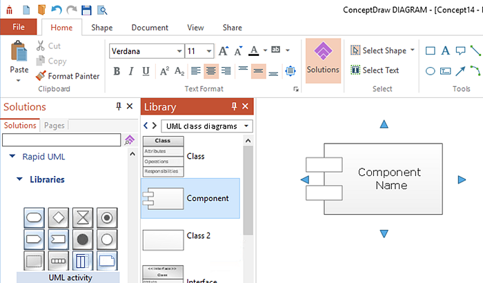
  1. Run ConceptDraw DIAGRAM.
  2. Reveal the Rapid UML item in the Solution panel.
  3. Activate appropriate UML libraries by clicking a library preview in the Solutions panel.
  4. Add your first object to the page.
  5. make uml diagram
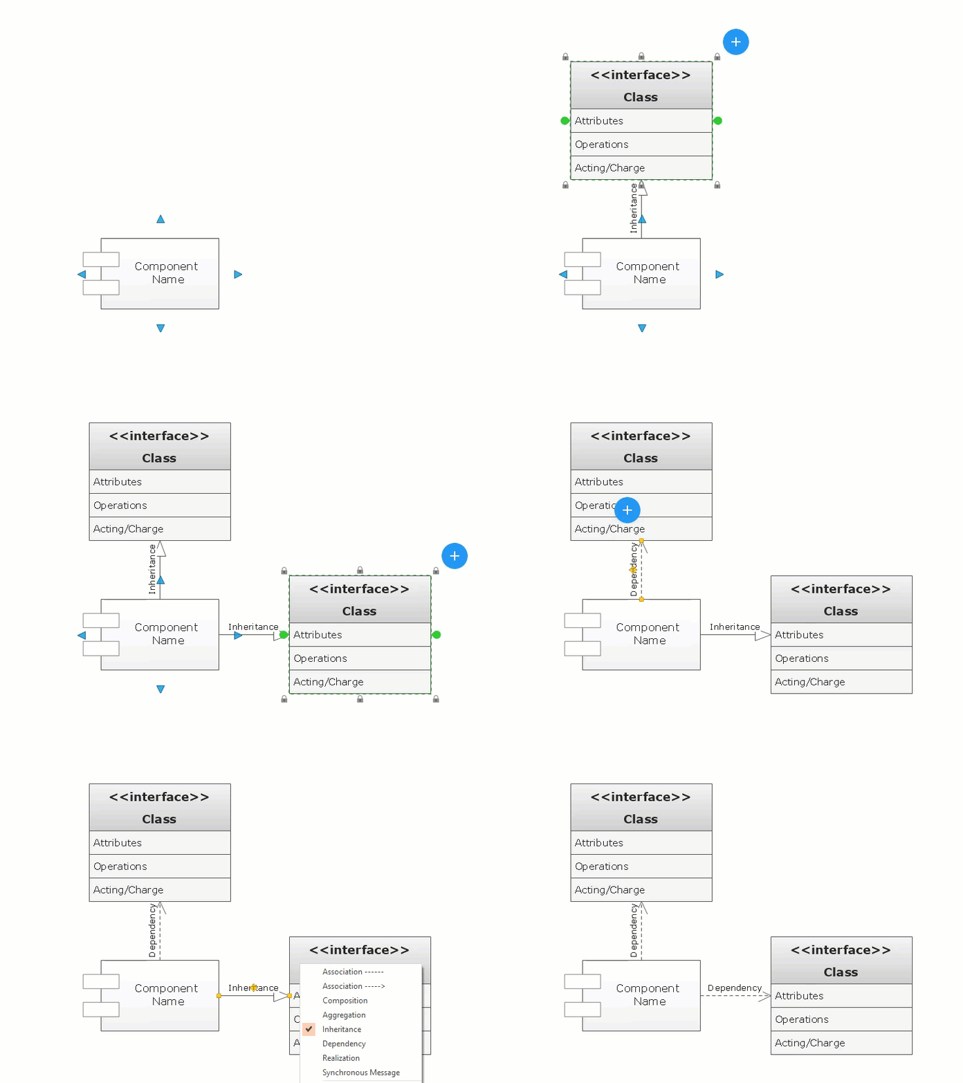
  6. Add the next object by clicking on its icon from the RapidDraw arrows that pop up when you bring the mouse cursor over the object.
  7. The new objects will be automatically drawn and connected to the previous ones.
  8. Use the Action button menu to assign possible properties to the UML elements.
  9. make uml diagram
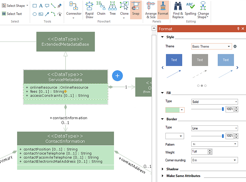
  10. Polish your diagram appearance using the tools provided in the Format panel.
  11. make uml diagram

Result:Using the RapidDraw technology to create diagrams allows you to make very complex diagrams quickly and easily.

How to Make a UML Diagram

How it works:

  • Set of ready-to-use templates supplied with ConceptDraw DIAGRAM
  • Collection of professional samples supports each template
  • Professional drawing tools

Useful Solutions and Products:

Rapid UML
  • UML diagrams samples and templates
  • Library of vector stencils

ConceptDraw DIAGRAM
  • Diagraming and Charts
  • Business Process diagrams
  • Business Process Modeling Notation (BPMN 2.0)
  • Business Model Presentation
  • Over 10 000 vector stencils
  • Export to vector graphics files
  • Export to Adobe Acrobat® PDF
  • Export to MS PowerPoint®
  • Export to MS Visio® VSDX, VDX

Products

  • ConceptDraw OFFICE v11
  • ConceptDraw DIAGRAM v18
  • ConceptDraw MINDMAP v16
  • ConceptDraw PROJECT v15
  • ConceptDraw STORE
  • ConceptDraw BOOKS

Solutions

  • Free
  • Premium

Samples

Support

  • Technical Support
  • Upgrade Request
  • Visio File Conversion
  • System Requirements
  • Helpdesk
  • Students & Educators
  • Enterprise
  • Customer Service

Solutions

  • Free
  • Premium

Samples

Video Room

  • Products
  • Solutions

Ready To Buy

  • Buy Online
  • Reseller Partners
  • Manage Your Account
  • Download Your Software
  • CS Odessa

    • About Us
    • Contact Us
    • CS Odessa Identity
    • News
  • CS Odessa
    Plan. Do. Communicate.

    About Us | Contact Us | Feedback | EULA | Privacy | TOU | TOS
    © 1993 — 2025 CS Odessa Corp.