Taxi Service Data Flow Diagram DFD Example

UML Use Case Diagram Example. Registration System

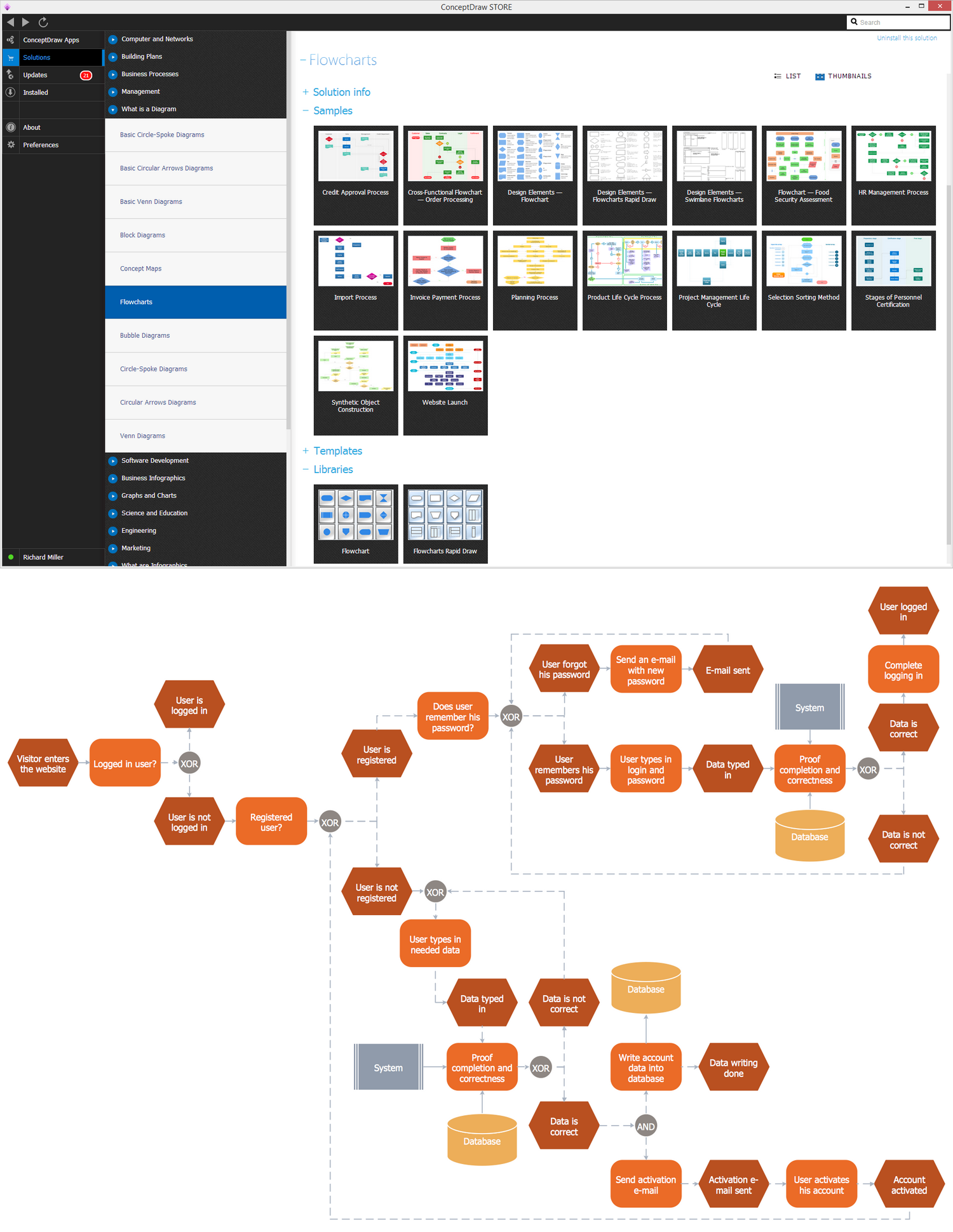
Data Flow Diagram Software

Flowchart
Interaction Overview Diagram


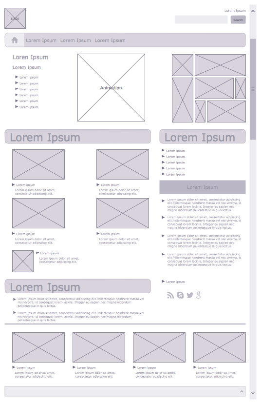
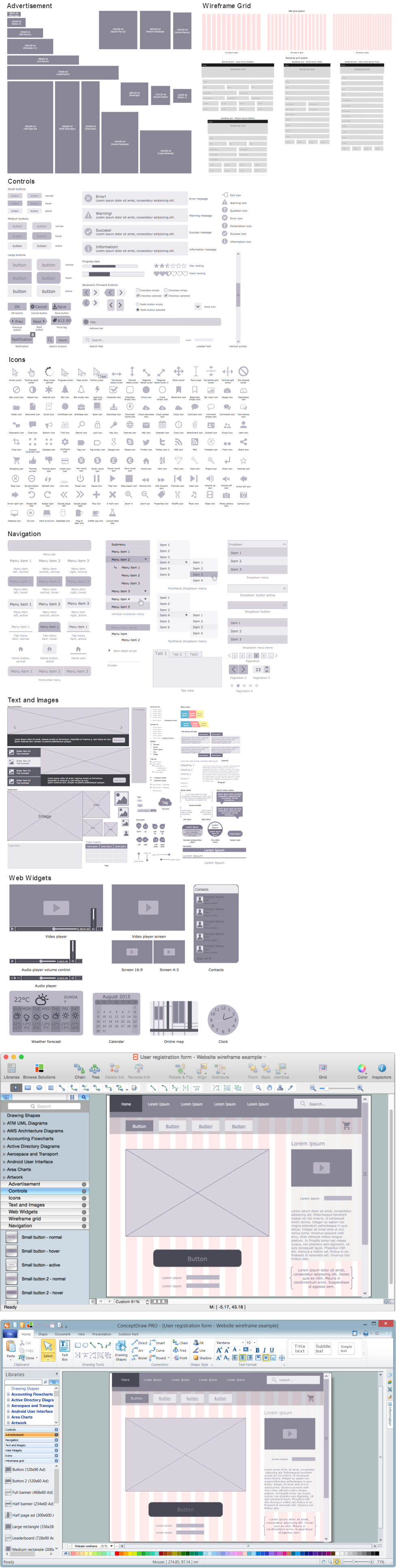
Wireframe Examples
Use Case Diagrams technology with ConceptDraw DIAGRAM

Garrett IA Diagrams with ConceptDraw DIAGRAM

Gane Sarson Diagram

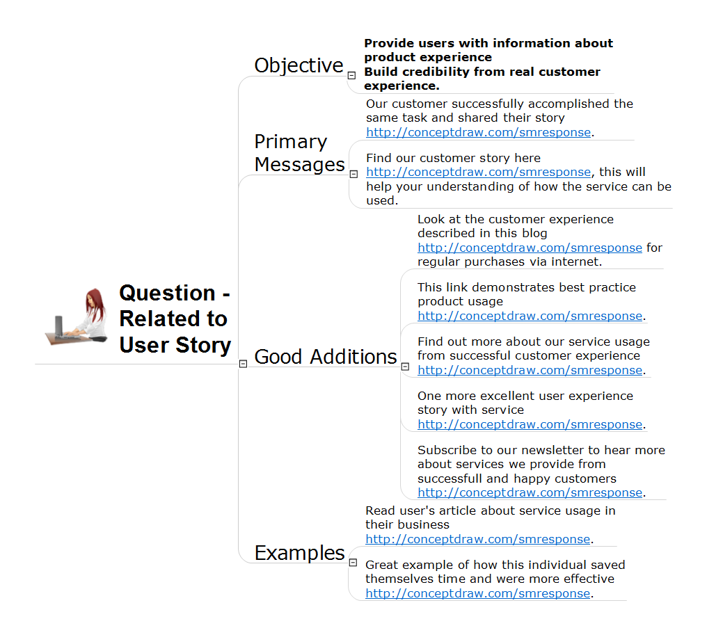
Address to User Story Question
Business process Flow Chart — Event-Driven Process chain (EPC) diagrams

Entity Relationship Diagram - ERD - Software for Design Crows Foot ER Diagrams
_Win_Mac.png)

UML Class Diagram. Design Elements

Wireframe Tools
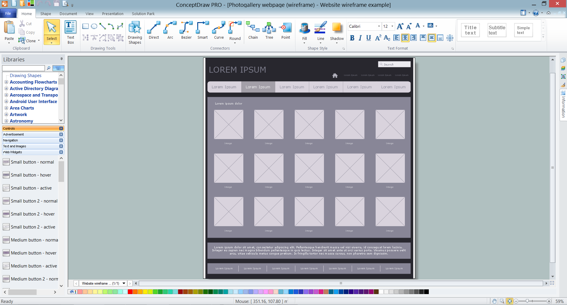
Wireframing
- Level 1 Dfd For User Registration
- Wireframe Examples | Registration And Verification Activities For Dfd
- Flowchart | UML Use Case Diagram Example Registration System ...
- Dfd For User Registration
- ER Diagram For User Register And Login
- Registration And Login Dfd
- UML Use Case Diagram Example Registration System | Example of ...
- UML Use Case Diagram Example Registration System | Word ...
- UML Use Case Diagram Example Registration System | Area Charts ...
- UML Use Case Diagram Example Registration System | 1st Level ...
- Process Flowchart | Data Flow Diagram | Basic Flowchart Symbols ...
- Data Flow Diagram For User Registration And Login
- Process Flowchart | UML Use Case Diagram Example Registration ...
- Design Of Dfd Of Registration Of New User
- Example of DFD for Online Store ( Data Flow Diagram ) DFD ...
- UML Use Case Diagram Example Registration System | Example of ...
- Interaction Overview Diagram | UML Use Case Diagram Example ...
- Level 1 Data Flow Diagram Examples For Students Registration
- Student Online Registration Dfd