Electrical Symbols — Lamps, Acoustics, Readouts

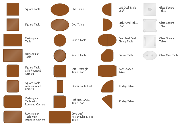
The design elements library Tables contains 27 symbols of tables.
Use the vector stencils library Tables to develop house floor plans, home designs, kitchen and dining room design and furniture layout of cafe or restaurant.
"A table is a form of furniture with a flat horizontal upper surface used to support objects of interest, for storage, show, and/ or manipulation. The surface must be held stable; for reasons of simplicity, this is usually done by support from below by either a column, a "base", or at least three columnar "stands". In special situations, table surfaces may be supported from a nearby wall, or suspended from above.
Common design elements include:
top surfaces of various shapes, including rectangular, rounded, or semi-circular;
legs arranged in two or more similar pairs;
several geometries of folding table that can be collapsed into a smaller volume;
heights ranging up and down from the most common 18–30 inches (46–76 cm) range, often reflecting the height of chairs or bar stools used as seating for people making use of a table, as for eating or performing various manipulations of objects resting on a table;
presence or absence of drawers;
expansion of the surface by insertion of leaves or locking hinged drop leaf sections into horizontal position.
Desks are tables specifically intended for information-manipulation tasks, including writing and use of interactive electronics.
Tables of various shapes, heights, and sizes are designed for specific uses:
Dining room tables are designed to be used for formal dining.
Bedside tables, nightstands, or night tables are small tables used in a bedroom. They are often used for convenient placement of a small lamp, alarm clock, glasses, or other personal items.
Gateleg tables have one or two hinged leaves supported by hinged legs.
Coffee tables are low tables designed for use in a living room, in front of a sofa, for convenient placement of drinks, books, or other personal items.
Refectory tables are long tables designed to seat many people for meals.
Drafting tables usually have a top that can be tilted for making a large or technical drawing. They may also have a ruler or similar element integrated.
Workbenches are sturdy tables, often elevated for use with a high stool or while standing, which are used for assembly, repairs, or other precision handwork.
Nested tables are a set of small tables of graduated size that can be stacked together, each fitting within the one immediately larger. They are for occasional use (such as a tea party), hence the stackable design." [Table (furniture). Wikipedia]
The shapes library Tables is provided by the Floor Plans solution from the Building Plans area of ConceptDraw Solution Park.
Interior Design. Office Layout Plan Design Element


Electrical Symbols, Electrical Schematic Symbols

Electrical Symbols — Resistors

Electrical Symbols — VHF UHF SHF

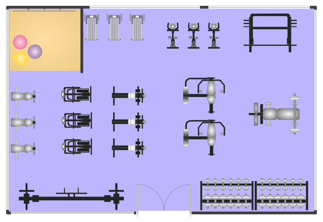
This electrical floor plan sample shows the lighting and switch layout.
"In building wiring, a light switch is a switch, most commonly used to operate electric lights, permanently connected equipment, or electrical outlets. Portable lamps such as table lamps will have a light switch mounted on the socket, base, or in-line with the cord. Manually operated on/ off switches may be substituted by remote control switches, or light dimmers that allow controlling the brightness of lamps as well as turning them on or off. Light switches are also found in flashlights and automobiles and other vehicles." [Light switch. Wikipedia]
The electrical floor plan example "Lighting and switch layout" was created using the ConceptDraw PRO diagramming and vector drawing software extended with the Electric and Telecom Plans solution from the Building plans area of ConceptDraw Solution Park.
Electrical floor plan

Electrical Symbols — Qualifying

Electrical Symbols — Delay Elements

Electrical Symbols — Logic Gate Diagram

Electrical Symbols — Rotating Equipment

Electrical Symbols — Integrated Circuit

Electrical Symbols — Composite Assemblies

Fitness Plans
Circuits and Logic Diagram Software

- Table Lamp And Floor Lamp Symbol
- Lighting and switch layout | Table Lamp Symbol For Lighting Plan
- Drawing Of Lamp In Floor Plan
- Table Lamp Symbol Furniture Layout Plan
- Furniture - Vector stencils library | The Symbol Of Desk Lamp And ...
- Symbol Of Lamps In A Floor Plan
- Furniture - Vector stencils library | Floor Plan Symbol For Tennis Table
- Floor Lamp Symbol
- Lighting Layout Symbols
- Symbol for Pool Table for Floor Plans | Template Restaurant Floor ...
- Wardrobe Light Plan Symbol
- Lighting and switch layout | Symbols Used For Vehicle Light Switches
- Design elements - Bedroom | Symbol for Pool Table for Floor Plans ...
- Lamp Symbols
- Symbol For A Wardrobe On A Floor Plan
- Dresser Symbols For Floor Plans
- Lighting and switch layout
- Radiator Symbol Floor Plan
- Floor Lamp Symbol On A Floor Plan
- Symbol Of Main Lighting Switch