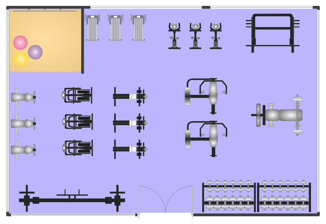
Example 1. Fitness Plans - Gym Layout Plan
Gym and Spa Area Plans Solution offers wide variety of ready-to-use predesigned templates and samples of Gym and Spa floor plans and layouts, and also 2 libraries with numerous vector objects:
- Spa library
- Physical Training library

Example 2. Physical Training Library Design Elements
Spa library contains 11 vector elements of Spa furniture and equipment for quick creating fitness plans with any degree of detailing for Spa centers and Spa resorts.

Example 3. Spa Library Design Elements
Physical Training library includes 17 vector objects of gym and exercise equipment for designing plans of equipment location in fitness centers and gym rooms.

Example 4. Fitness Plans - Gym Floor Plan
The Fitness Plans you see on this page were created in ConceptDraw DIAGRAM using the tools of Gym and Spa Area Plans Solution. These samples demonstrate ConceptDraw DIAGRAM software capabilities, and the professional results you can achieve quick and easy. An experienced user spent 10-15 minutes creating every of these samples.
The Fitness Plans created with ConceptDraw DIAGRAM are vector graphic documents and are available for reviewing, modifying, and converting to a variety of formats (image, HTML, PDF file, MS PowerPoint Presentation, Adobe Flash or MS Visio).
TEN RELATED HOW TO's:
The critical importance of house electrical plans. 🔸 Learn how to create efficient electrical layouts using the ConceptDraw DIAGRAM app. Enhance ✔️ safety, ✔️ functionality, and ✔️ compliance with electrical codes in your home projects with our comprehensive guide
Picture:
Importance of House Electrical Plans
How to Create Electrical Layouts
with ConceptDraw DIAGRAM App
Related Solution:
While studying, many of the students encounter the necessity of remaking class projects, over and over. To facilitate this process you can use special electrical and telecom plan software, which helps altering projects in several clicks. Using templates will fasten your work, and you will have more free time.
This sample represents an electrical and telecommunication floor plan. Electrical and telecom floor plans contain a floor plan , on which imposed the layout of electrical, and telecommunications equipment. They shows electrical and telecom details regarding the current floor of a building: lightening, fixtures, wires, outlets, circuit panels, etc. Using of standart notation of electrical and telecommunication symbols makes the plan understandable for engineers, architects, constructors, specialist in electricity and telecommunications.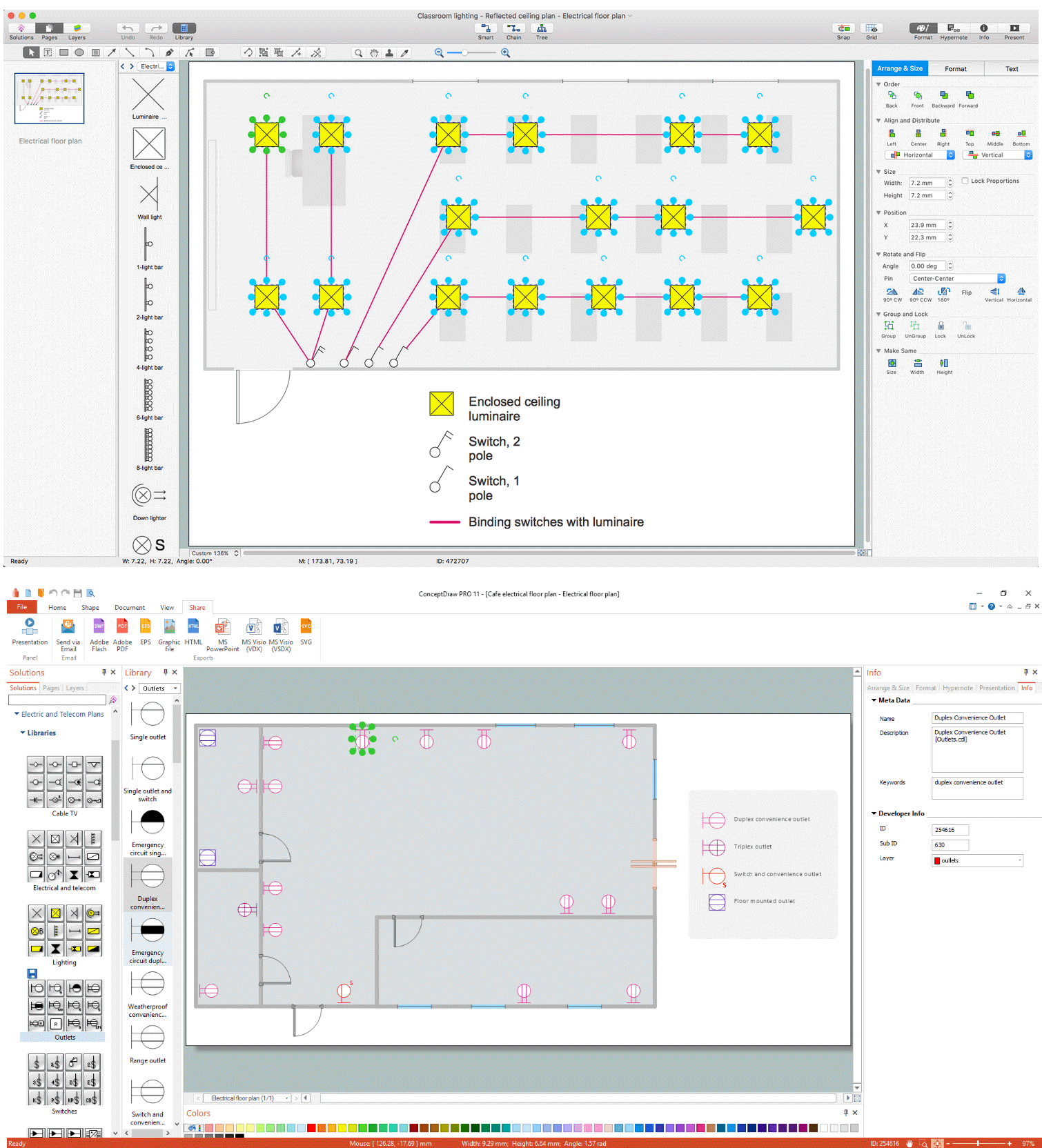
Picture: Electrical and Telecom Plan Software
Related Solution:
To connect two or more network devices are used the network cables. There are more different types of the network cables: Coaxial cable, Optical fiber cable, Twisted Pair, Ethernet crossover cable, Power lines and others. They are used depending of the network topology, size, protocol.
This example was created in ConceptDraw DIAGRAM using the Computer and Networks solution from the Computer and Networks area of ConceptDraw Solution Park.
Picture: Network wiring cable. Computer and Network Examples
Related Solution:
Sometimes, it's not easy to fit everything you need into your premise. So, you can discover how to use building plan examples and get inspired from viewing them. You can find a lot of office layout and floor plans templates in the ConceptDraw Solution Park.
This drawing shows the sample of interior design of a middle-size restaurant. It was designed with a help of ConceptDraw Cafe and Restaurant Plans solution. Extensive libraries of vector objects of the interior element enabled us to design this example quickly and with no efforts. You can use this interior plan as a template while designing an interior for your own restaurant. It will help you to compose and organize elements of the interior, to bring a balance between free space and furniture in your establishment. It can be applied to organize and arrange the furniture, equipment and decorative elements in the restaurant interior and achieve balance between furniture and free space.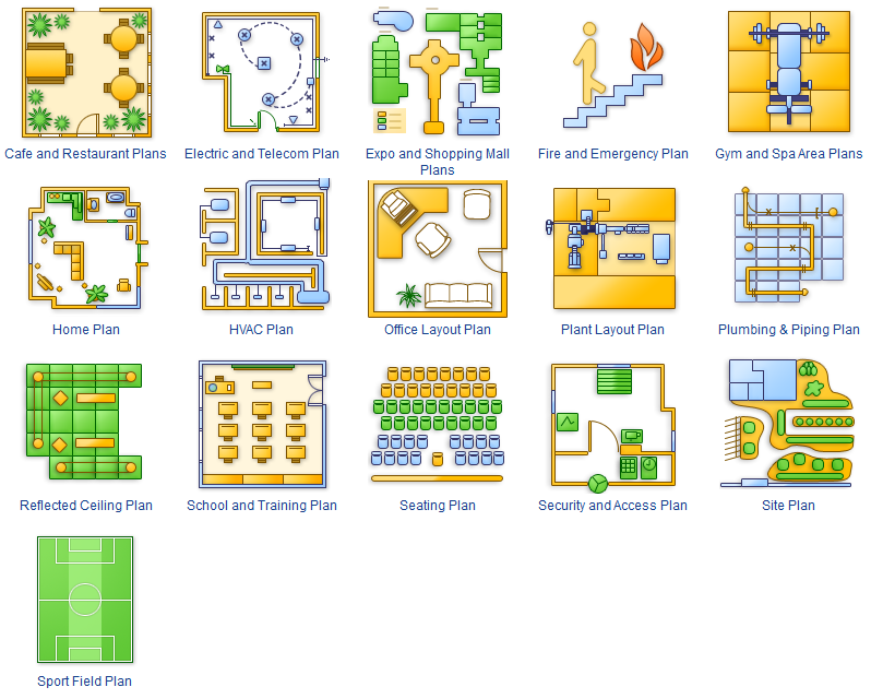
Picture: How To use Building Plan Examples
Related Solution:
The ConceptDraw Home Design Software extended with Floor Plans solution from the Building Plans area of ConceptDraw Solution Park offers the powerful tools which will help you in easy developing vivid and professional-looking: Building plans, Home plans, House designs, Floor plans, Home interior designs, Furniture and equipment layouts.
Picture: Home Design Software
Related Solution:
Design of any premises includes many stages and variety of plans. Ceiling plans are also included in this number. Reflected Ceiling Plans Solution from the Building Plans Area for ConceptDraw DIAGRAM software will help you represent and realize any of your ceiling ideas for living room.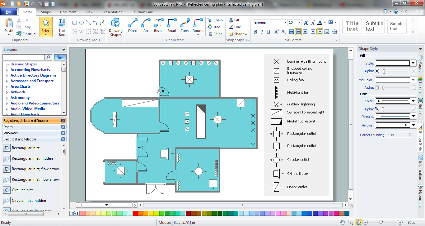
Picture: Ceiling Ideas For Living Room
Related Solution:
When trying to figure out the nature of the problems occurring within a project, there are many ways to develop such understanding. One of the most common ways to document processes for further improvement is to draw a process flowchart, which depicts the activities of the process arranged in sequential order — this is business process management. ConceptDraw DIAGRAM is business process mapping software with impressive range of productivity features for business process management and classic project management. This business process management software is helpful for many purposes from different payment processes, or manufacturing processes to chemical processes. Business process mapping flowcharts helps clarify the actual workflow of different people engaged in the same process. This samples were made with ConceptDraw DIAGRAM — business process mapping software for flowcharting and used as classic visio alternative because its briefly named "visio for mac" and for windows, this sort of software named the business process management tools.
This flowchart diagram shows a process flow of project management. The diagram that is presented here depicts the project life cycle that is basic for the most of project management methods. Breaking a project into phases allows to track it in the proper manner. Through separation on phases, the total workflow of a project is divided into some foreseeable components, thus making it easier to follow the project status. A project life cycle commonly includes: initiation, definition, design, development and implementation phases. Distinguished method to show parallel and interdependent processes, as well as project life cycle relationships. A flowchart diagram is often used as visual guide to project. For instance, it used by marketing project management software for visualizing stages of marketing activities or as project management workflow tools. Created with ConceptDraw DIAGRAM — business process mapping software which is flowcharting visio alternative or shortly its visio for mac, this sort of software platform often named the business process management tools.
Picture: Process Flowchart: A Step-by-Step Comprehensive Guide
Related Solution:
Cafes and restaurants are the places for relax and recreation, so the most important is their design and atmosphere of comfort, harmony, and uniqueness. So Cafe Design requires great creativity and efforts from the designers. ConceptDraw DIAGRAM software extended with Cafe and Restaurant Floor Plan solution from the Building Plans area of ConceptDraw Solution Park is the most simple way of displaying your Cafe Design ideas and plans first on the computer screen, and then on the paper.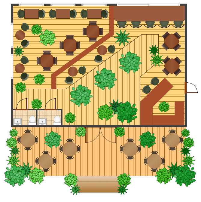
Picture: Cafe Design
Related Solution:
Talking about interior design, we usually mean apartments, houses or establishments. But there’s much more to this, for instance, interiors in warehouses, storage and distribution departments and machine shops also require designing. You can find all the necessary design elements such as cranes and forklifts in Plant Layout Plans solution ConceptDraw Solution Park.
This picture represents content of the Storage and Distribution library, providing the collection of vector images designed to plan layouts of industrial storage facilities (warehouses). Warehouse is a premises and equipment intended for the reception, distribution and storage of products manufactured at the plant, as well as to preparation the product for shipment to the consumer. This vector images library is supplied with ConceptDraw Plant Layout Plans solution. it will help to industrial architects and planners to design plans for industrial storage and shipping facilities.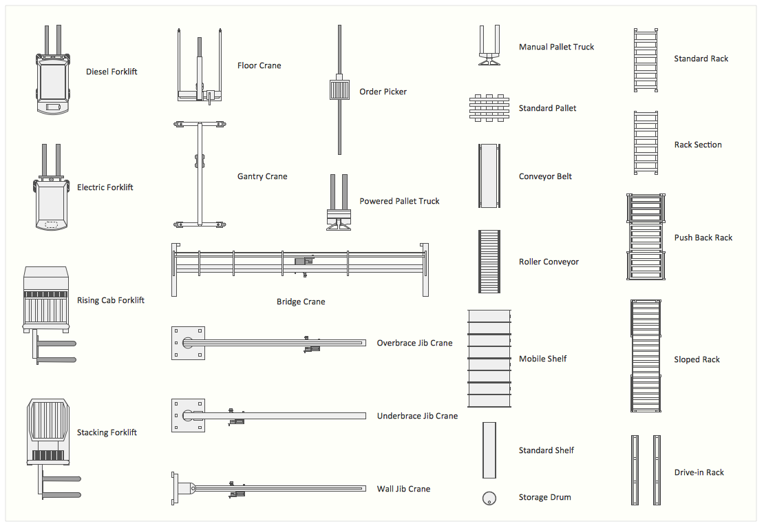
Picture: Interior Design. Storage and Distribution — Design Elements
Related Solution:
Below you can see the symbol for pool table. You can find this symbol in the library of the Floor Plans Solution and use it in your floor plan of the sport complex, home, etc.
ConceptDraw DIAGRAM is a powerful diagramming and vector drawing software for creating the different Floor Plans. It’s very convenient, simple and quick to design the professional looking Floor Plans of any difficulty in ConceptDraw DIAGRAM.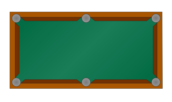
Picture: Symbol for Pool Table for Floor Plans
Related Solution:


