Electrical Symbols — Thermo

How To use House Electrical Plan Software


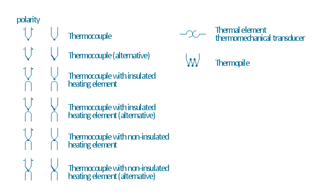
The vector stencils library "Thermo" contains 14 symbols of thermoelectric elements: thermal element, thermocouples with and without heating elements, thermoplile.
Use it for drawing electrical layouts, electronic schematics, and circuit diagrams.
"The thermoelectric effect is the direct conversion of temperature differences to electric voltage and vice versa. A thermoelectric device creates voltage when there is a different temperature on each side. Conversely, when a voltage is applied to it, it creates a temperature difference. At the atomic scale, an applied temperature gradient causes charge carriers in the material to diffuse from the hot side to the cold side.
This effect can be used to generate electricity, measure temperature or change the temperature of objects. Because the direction of heating and cooling is determined by the polarity of the applied voltage, thermoelectric devices can be used as temperature controllers.
The term "thermoelectric effect" encompasses three separately identified effects: the Seebeck effect, Peltier effect, and Thomson effect. Textbooks may refer to it as the Peltier–Seebeck effect. ...
Thermocouples and thermopiles are devices that use the Seebeck effect to measure the temperature difference between two objects, one connected to a voltmeter and the other to the probe. The temperature of the voltmeter, and hence that of the material being measured by the probe, can be measured separately using cold junction compensation techniques." [Thermoelectric effect. Wikipedia]
The shapes example "Design elements - Thermo" was drawn using the ConceptDraw PRO diagramming and vector drawing software extended with the Electrical Engineering solution from the Engineering area of ConceptDraw Solution Park.
Thermoelectric elements
The vector stencils library "Heating equipment" contains 42 symbols of regenerators, intercoolers, heaters, and condensers.
Use these shapes for drawing cooling systems, heat recovery systems, thermal, heat transfer and mechanical design, and process flow diagrams (PFD).
"Heating or cooling of processes, equipment, or enclosed environments are within the purview of thermal engineering.
One or more of the following disciplines may be involved in solving a particular thermal engineering problem:
Thermodynamics,
Fluid mechanics,
Heat transfer,
Mass transfer.
Thermal engineering may be practiced by mechanical engineers and chemical engineers.
One branch of knowledge used frequently in thermal engineering is that of thermofluids." [Thermal engineering. Wikipedia]
The design elements example "Heating equipment" was created using the ConceptDraw PRO diagramming and vector drawing software extended with the Chemical and Process Engineering solution from the Engineering area of ConceptDraw Solution Park.
Heating equipment symbols

The vector stencil library "HVAC equipment" contains 84 HVAC equipment symbols as pumps, fans, condensers, pipe coils, silencers, etc.
Use it for drawing HVAC system diagrams, heating, ventilation, air conditioning, refrigeration, automated building control, and environmental control design floor
plans and equipment layouts.
"HVAC (heating, ventilation, and air conditioning) is the technology of indoor and vehicular environmental comfort. HVAC system design is a subdiscipline of mechanical engineering, based on the principles of thermodynamics, fluid mechanics, and heat transfer. Refrigeration is sometimes added to the field's abbreviation as HVAC&R or HVACR, or ventilating is dropped as in HACR (such as the designation of HACR-rated circuit breakers).
HVAC is important in the design of medium to large industrial and office buildings such as skyscrapers and in marine environments such as aquariums, where safe and healthy building conditions are regulated with respect to temperature and humidity, using fresh air from outdoors." [HVAC. Wikipedia]
The vector stencils example "Design elements - HVAC equipment" is included in HVAC Plans solution from the Building Plans area of ConceptDraw Solution Park.
HVAC equipment symbols

Process Flow Diagram Symbols

Electrical Symbols, Electrical Diagram Symbols

The vector stencils library "Thermo" contains 14 symbols of thermoelectric elements.
Use these shapes for drawing electrical layouts, electronic schematics, and circuit diagrams in the ConceptDraw PRO diagramming and vector drawing software extended with the Electrical Engineering solution from the Engineering area of ConceptDraw Solution Park.
www.conceptdraw.com/ solution-park/ engineering-electrical
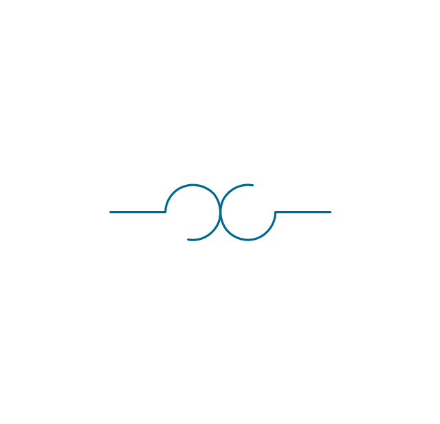
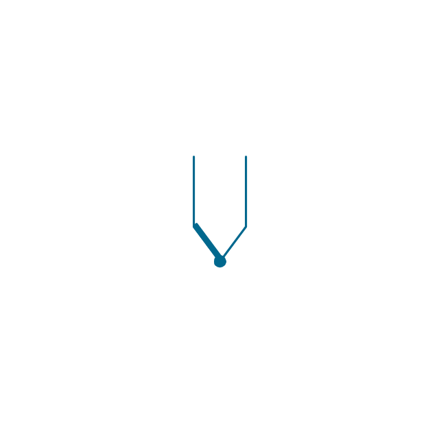
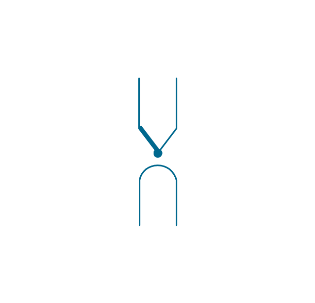
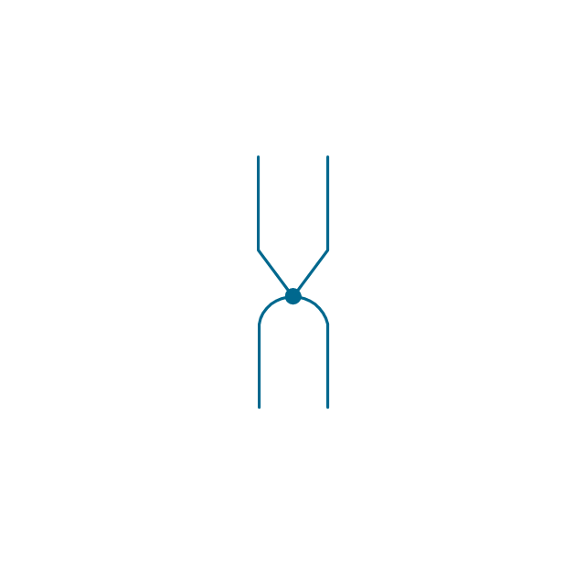
Thermal element
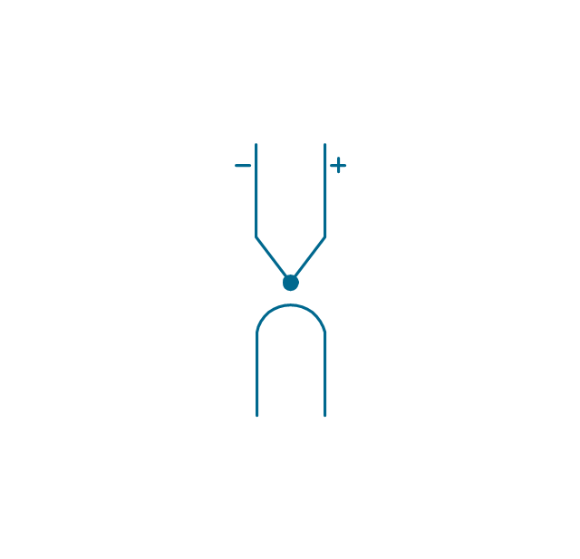
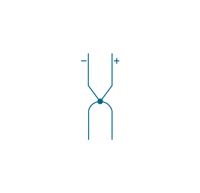
Thermocouple, polarity
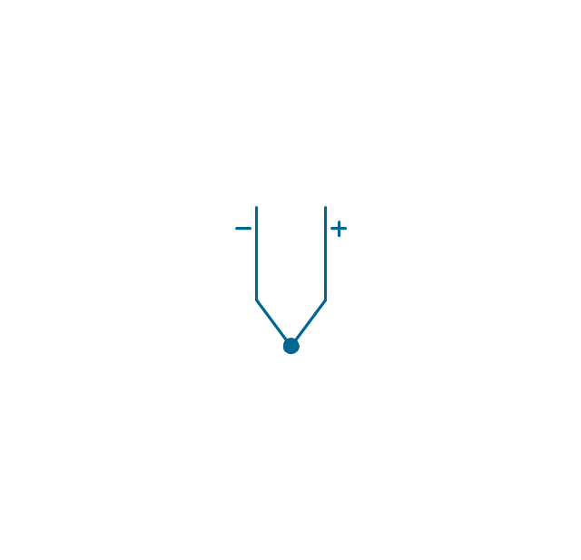
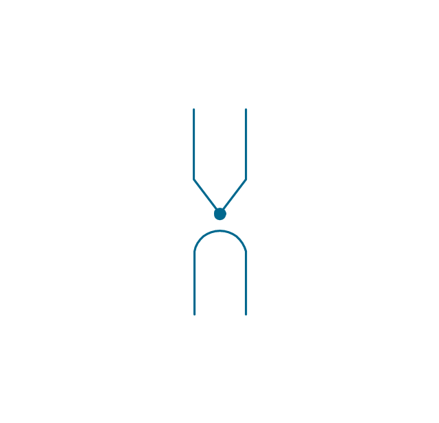
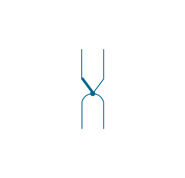
Thermocouple
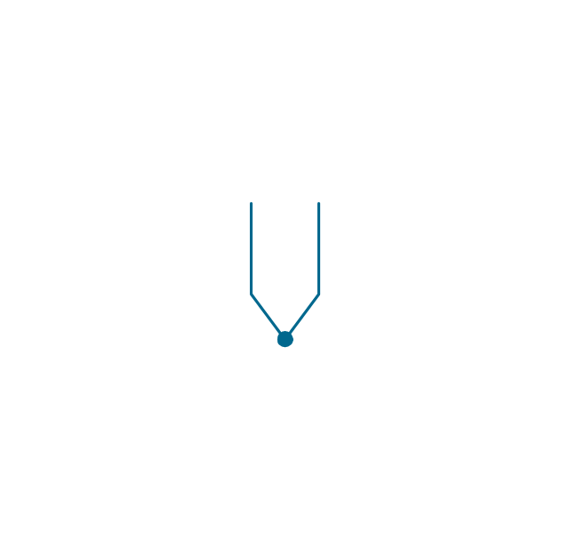
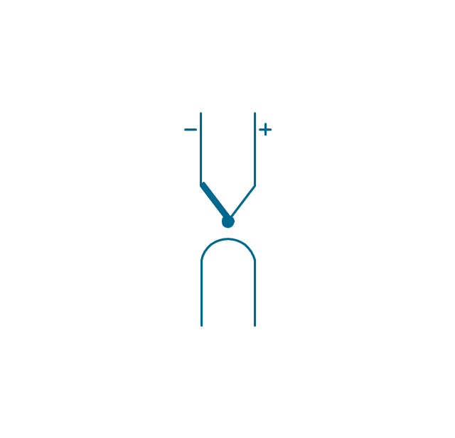
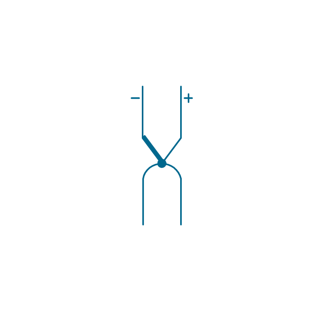
Thermocouple, polarity

Thermocouple
Thermocouple with insulated heating element, polarity
Thermocouple with insulated heating element
Thermocouple with insulated heating element, polarity
Thermocouple with insulated heating element
Thermocouple with non-insulated heating element, polarity
Thermocouple with non-insulated heating element, polarity
Thermocouple with non-insulated heating element
Thermocouple with non-insulated heating element
Thermopile

The vector stencil library "HVAC controls" contains contains 24 HVAC control symbols: sensors, actuators, timers, controllers, I/ O points.
Use it for drawing HVAC system diagrams, heating, ventilation, air conditioning, refrigeration, automated building control, and environmental control design floor
plans and equipment layouts.
"HVAC (... Heating, Ventilation and Air Conditioning) is a control system that applies regulation to a heating and/ or air conditioning system. ...
Central controllers and most terminal unit controllers are programmable, meaning the direct digital control program code may be customized for the intended use. The program features include time schedules, setpoints, controllers, logic, timers, trend logs, and alarms. The unit controllers typically have analog and digital inputs that allow measurement of the variable (temperature, humidity, or pressure) and analog and digital outputs for control of the transport medium (hot/ cold water and/ or steam). Digital inputs are typically (dry) contacts from a control device, and analog inputs are typically a voltage or current measurement from a variable (temperature, humidity, velocity, or pressure) sensing device. Digital outputs are typically relay contacts used to start and stop equipment, and analog outputs are typically voltage or current signals to control the movement of the medium (air/ water/ steam) control devices such as valves, dampers, and motors." [HVAC control system. Wikipedia]
The vector stencils example "Design elements - HVAC controls" is included in HVAC Plans solution from the Building Plans area of ConceptDraw Solution
Park.
HVAC control symbols

The vector stencils library "Plumbing" contains 32 symbols of plumbing components and bathroom fixtures.
"Plumbing is the system of pipes, drains fittings, valves, valve assemblies, and devices installed in a building for the distribution of water for drinking, heating and washing, and the removal of waterborne wastes, and the skilled trade of working with pipes, tubing and plumbing fixtures in such systems. A plumber is someone who installs or repairs piping systems, plumbing fixtures and equipment such as water heaters and backflow preventers. The plumbing industry is a basic and substantial part of every developed economy due to the need for clean water, and sanitary collection and transport of wastes.
Plumbing is usually distinguished from water supply and sewage systems, in that a plumbing system serves one building, while water and sewage systems serve a group of buildings." [Plumbing. Wikipedia]
Use the design elements library "Plumbing" for drawing plumbing and piping plans, schematic diagrams and blueprints of waste water disposal systems, and hot and cold water supply systems using the ConceptDraw PRO diagramming and vector drawing software.
The shapes library "Plumbing" is included in the Plumbing and Piping Plans solution from the Building Plans area of ConceptDraw Solution Park.
Plumbing symbols

Interior Design. Plumbing — Design Elements

Mechanical Drawing Symbols

Electrical Symbols — Inductors

The vector stencil library "HVAC control equipment" contains 81 HVAC control equipment icons.
Use it for drawing HVAC system diagrams, heating, ventilation, air conditioning, refrigeration, automated building control, and environmental control design floor
plans and equipment layouts.
"HVAC (stands for Heating, Ventilation and Air Conditioning) is a control system that applies regulation to a heating and/ or air conditioning system. Usually a sensing device is used to compare the actual state (e.g., temperature) with a target state. Then the control system draws a conclusion what action has to be taken (e.g., start the blower).
More complex HVAC systems can interface to Building Automation System (BAS) to allow the building owners to have more control over the heating or cooling units. The building owner can monitor the system and respond to alarms generated by the system from local or remote locations." [HVAC control system. Wikipedia]
The vector stencils example "Design elements - HVAC control equipment" is included in HVAC Plans solution from the Building Plans area of ConceptDraw Solution
Park.
HVAC control equipment symbols

The vector stencil library "HVAC ductwork" contains 63 duct and vent symbols.
Use it for drawing HVAC system diagrams, heating, ventilation, air conditioning, refrigeration, automated building control, and environmental control design floor
plans and equipment layouts.
"Ducts are used in heating, ventilation, and air conditioning (HVAC) to deliver and remove air. These needed airflows include, for example, supply air, return air, and exhaust air. Ducts also deliver, most commonly as part of the supply air, ventilation air. As such, air ducts are one method of ensuring acceptable indoor air quality as well as thermal comfort.
A duct system is often called ductwork. Planning ('laying out'), sizing, optimizing, detailing, and finding the pressure losses through a duct system is called duct design." [Duct (HVAC). Wikipedia]
The vector stencils example "Design elements - HVAC ductwork" is included in HVAC Plans solution from the Building Plans area of ConceptDraw Solution Park.
HVAC ductwork symbols

Electrical Symbols — Switches and Relays

Electrical Symbols, Electrical Schematic Symbols

Electrical Symbols — Maintenance

The vector stencils library "HVAC control equipment" contains 48 HVAC symbols. Use it for drawing HVAC systems diagrams, heating, ventilation, air conditioning, refrigeration, automated building control, and environmental control design building plans and equipment layouts. The symbols example "HVAC control equipment - Vector stencils library" was created using the ConceptDraw PRO diagramming and vector drawing software extended with the HVAC Plans solution from the Building Plans area of ConceptDraw Solution Park.
Duct, sgl line

Duct, dbl line

Return duct, sgl line

Return duct, dbl line

Supply duct, sgl line

Supply duct, dbl line

Return duct 2, sgl line

Return duct 2, dbl line

Supply duct extension, sgl line

Supply duct extension, dbl line

Return duct extension, sgl line

Return duct extension, dbl line

2-fan section, sgl line

2-fan section, dbl line

3-fan section, sgl line

3-fan section, dbl line

4-fan section, sgl line

4-fan section, dbl line

VAV box

DD-VAV box

Fan coil housing

Unit heater

Centrifugal fan

Propeller fan

Vane axial fan

Damper

Filter

Air flow station

Humidifier

Htg/clg coil

Valve

Water flow meter

Pump


Cooling tower

Converter

Heat exchanger

Boiler

Equipment

Starter

VSD

Side to bottom pipe

Side to bottom pipe, arrow
Side to side pipe

Side to side pipe, arrow
Top to bottom pipe

Top to bottom pipe, arrow
Pipe flow arrow
The vector stencils library "Plumbing" contains 31 symbols of plumbing components and bathroom fixtures. Use it for dawing plumbing and piping plans, schematic diagrams, blueprints of waste water disposal systems, hot and cold water supply systems in the ConceptDraw PRO diagramming and vector drawing software extended with the Plumbing and Piping Plans solution from the Building Plans area of ConceptDraw Solution Park.
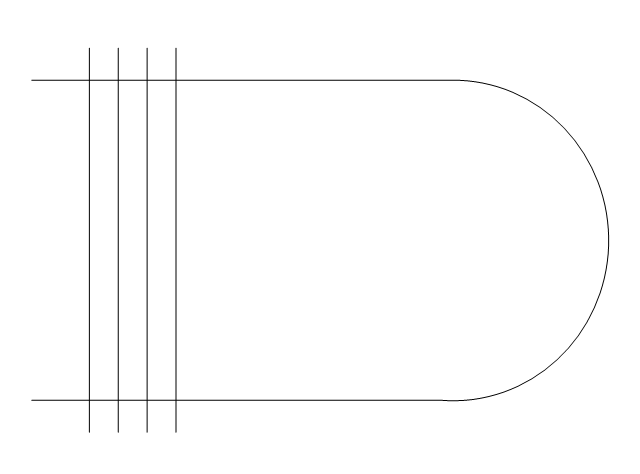
Boiler, flat ends
Boiler, curved ends
Boiler, angled ends
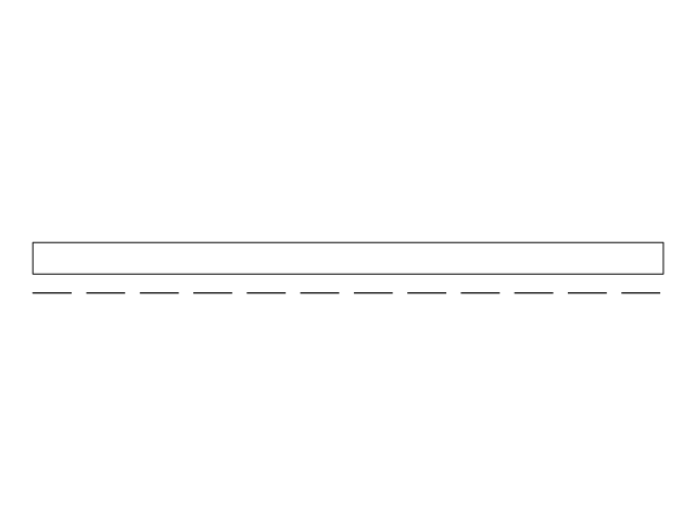
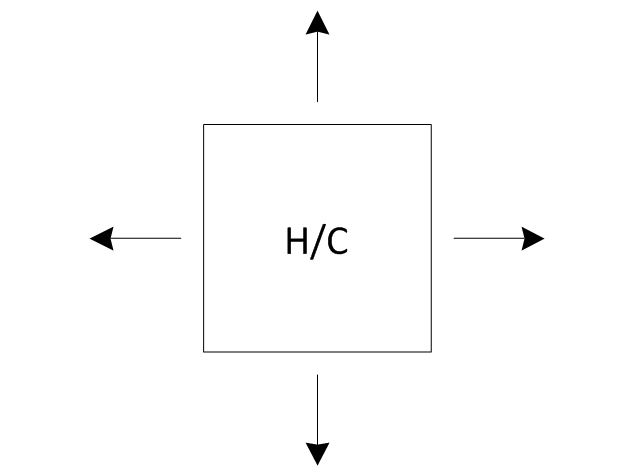
Heating/Cooling coil
Pump
Pump
Radiator
Convector
Convector, fan
Radiant panel (plan), sgl
,-sgl-plumbing---vector-stencils-library.png--diagram-flowchart-example.png)
Radiant panel (plan), dbl
,-dbl-plumbing---vector-stencils-library.png--diagram-flowchart-example.png)
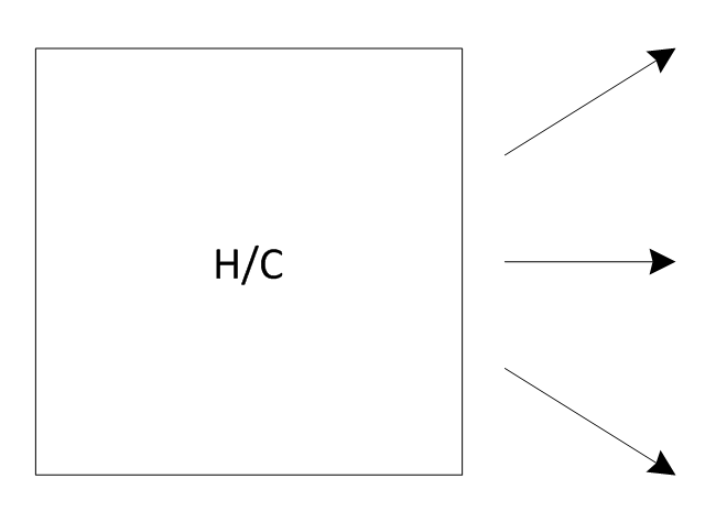
Heater/cooler, horizontal
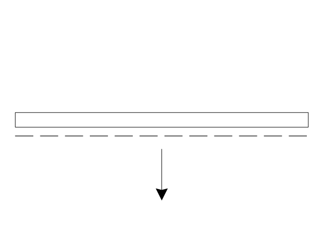
Heater/cooler, downward
Radiant panel (face)
-plumbing---vector-stencils-library.png--diagram-flowchart-example.png)
Tank, open
Tank, closed
Water surface
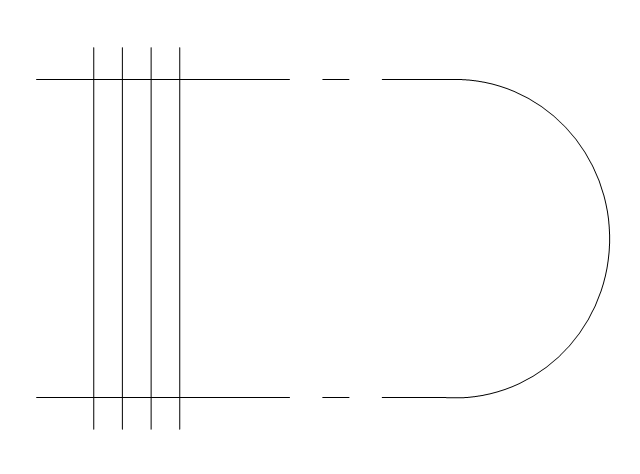
Pipe coils
Pipe coils, fins
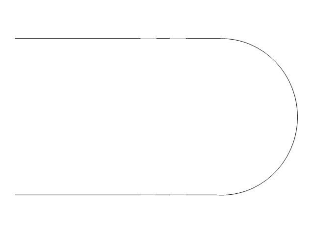
Pipe coils, break
Pipe coils, break, fins
Sink unit
Basin
Toilet
Bath
Basin (side)
-plumbing---vector-stencils-library.png--diagram-flowchart-example.png)
Toilet (side)
-plumbing---vector-stencils-library.png--diagram-flowchart-example.png)
Bath (side)
-plumbing---vector-stencils-library.png--diagram-flowchart-example.png)
End view
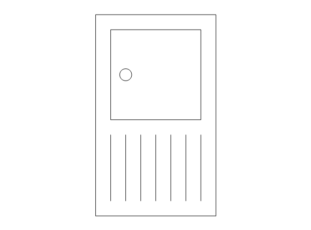
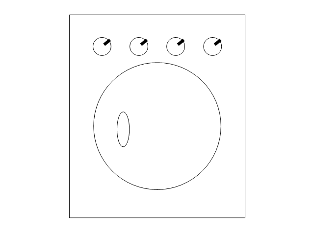
Washing machine
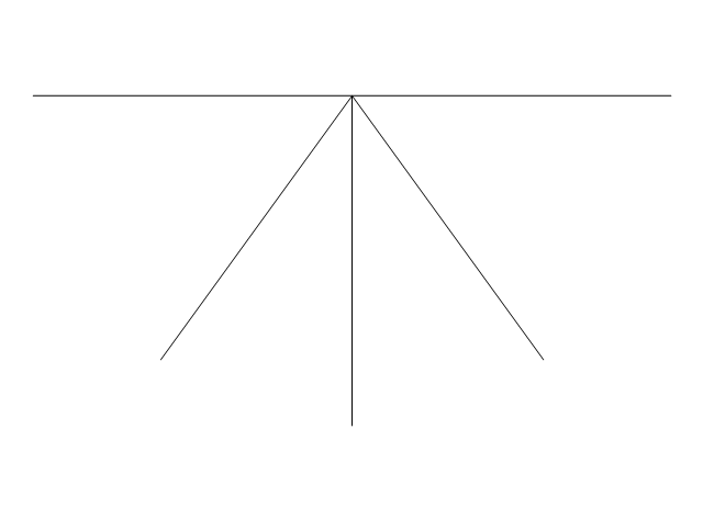
Shower head
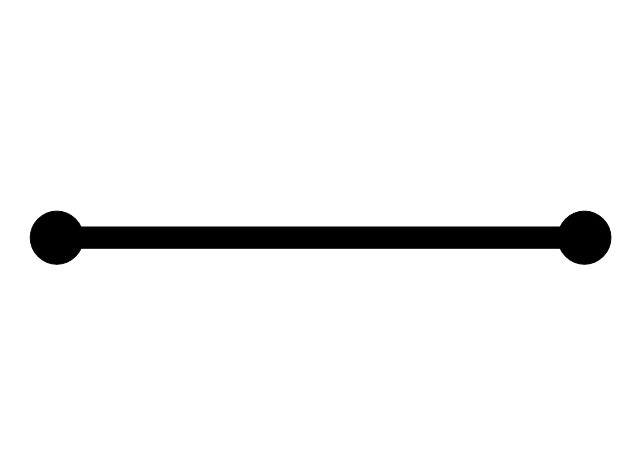
Towel rail
- Heating Element Symbols
- Heating Element Schematic Symbol
- Electrical Symbols — Thermo | Electrical Symbols — Resistors ...
- Process Flow Diagram Symbols | Design elements - Heating ...
- Heating Element Symbol On Wiring Diagrams
- Schematic Symbol Of Heating Coil
- Design elements - Appliances | What Is The Electrical Symbol For ...
- Design elements - Heating equipment | Plumbing and Piping Plans ...
- Electrical Symbols — Thermo | Thermo - Vector stencils library ...
- Heating Element Schematic
- Interior Design. Plumbing — Design Elements | Heater Electrical ...
- Design elements - Appliances | Design elements - Plumbing ...
- Heater Element Symbol
- Design elements - Heating equipment | Heating equipment - Vector ...
- Draw A Type Of A Heating Element
- Design elements - Heating equipment | Design elements - HVAC ...
- Heating equipment - Vector stencils library | Design elements ...
- Design elements - HVAC controls | Design elements - Valves ...
- Heat Vent Symbol For Floor Plan
- Design elements - Heating equipment | Chemical and Process ...