The vector stencils library "Heating equipment" contains 42 symbols of regenerators, intercoolers, heaters, and condensers.
Use these shapes for drawing cooling systems, heat recovery systems, thermal, heat transfer and mechanical design, and process flow diagrams (PFD).
"Heating or cooling of processes, equipment, or enclosed environments are within the purview of thermal engineering.
One or more of the following disciplines may be involved in solving a particular thermal engineering problem:
Thermodynamics,
Fluid mechanics,
Heat transfer,
Mass transfer.
Thermal engineering may be practiced by mechanical engineers and chemical engineers.
One branch of knowledge used frequently in thermal engineering is that of thermofluids." [Thermal engineering. Wikipedia]
The design elements example "Heating equipment" was created using the ConceptDraw PRO diagramming and vector drawing software extended with the Chemical and Process Engineering solution from the Engineering area of ConceptDraw Solution Park.
Heating equipment symbols

Mechanical Drawing Symbols

Process Flow Diagram Symbols

The vector stencil library "HVAC control equipment" contains 81 HVAC control equipment icons.
Use it for drawing HVAC system diagrams, heating, ventilation, air conditioning, refrigeration, automated building control, and environmental control design floor
plans and equipment layouts.
"HVAC (stands for Heating, Ventilation and Air Conditioning) is a control system that applies regulation to a heating and/ or air conditioning system. Usually a sensing device is used to compare the actual state (e.g., temperature) with a target state. Then the control system draws a conclusion what action has to be taken (e.g., start the blower).
More complex HVAC systems can interface to Building Automation System (BAS) to allow the building owners to have more control over the heating or cooling units. The building owner can monitor the system and respond to alarms generated by the system from local or remote locations." [HVAC control system. Wikipedia]
The vector stencils example "Design elements - HVAC control equipment" is included in HVAC Plans solution from the Building Plans area of ConceptDraw Solution
Park.
HVAC control equipment symbols

Electrical Symbols — Stations

Interior Design. Plumbing — Design Elements

Cisco Network Design. Cisco icons, shapes, stencils, symbols and design elements

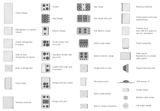
The vector stencils library Appliances contains 36 symbols of kitchen appliances, laundry appliances, stoves, cooking appliances, and laundry equipment.
Use the shapes library Appliances to draw equipment layouts and interior design floor plans of kitchens, laundry rooms, utility rooms using the ConceptDraw PRO diagramming and vector drawing software.
"Home appliances are electrical/ mechanical machines which accomplish some household functions, such as cooking or cleaning. Home appliances can be classified into:
Major appliances, or White goods;
Small appliances, or Brown goods;
Consumer electronics, or Shiny goods.
White goods/ major appliances comprise major household appliances and may include: air conditioner, dishwasher, clothes dryer, drying cabinet, freezer, refrigerator, kitchen stove, water heater, washing machine, trash compactor, microwave ovens and induction cookers.
Brown goods/ small appliances are typically small household electrical entertainment appliances such as: TV sets, CD and DVD players, camcorders, still cameras, clocks, alarm clocks, video game consoles, HiFi and home cinema, telephones and answering machines.
Consumer electronics (abbreviated CE) are electronic equipment intended for everyday use, most often in entertainment, communications and office productivity. Main products include radio receivers, television sets, MP3 players, video recorders, DVD players, digital cameras, camcorders, personal computers, video game consoles, telephones and mobile phones." [Home appliance. Wikipedia]
The design elements library Appliances is provided by the Floor Plans solution from the Building Plans area of ConceptDraw Solution Park.
The vector stencils library "Heating equipment" contains 42 symbols of regenerators, intercoolers, heaters, and condensers.
Use these shapes for drawing cooling systems, heat recovery systems, thermal, heat transfer and mechanical design, and process flow diagrams (PFD) in the ConceptDraw PRO software extended with the Chemical and Process Engineering solution from the Chemical and Process Engineering area of ConceptDraw Solution Park.
www.conceptdraw.com/ solution-park/ engineering-chemical-process
Heat exchanger 3

Heat exchanger 1

Heat exchanger 2

Tube bundle, floating head

U-Tube bundle

Tube bundle

Shell and tube

Kettle reboiler

Plate type

Finned tube

Double pipe type

Oil burner

Boiler

Fired heater

Cooling tower 2

Cooling tower 1

Cooling tower 3

Condenser

Automatic stoker

Refrigerator

Direct refrigerator

Indirect refrigerator

Evaporative condenser

Condenser (air cooled)
-heating-equipment---vector-stencils-library.png--diagram-flowchart-example.png)
Oil separator

Chilling evaporator

Air cooling evaporator

Extractor hood (slot)
-heating-equipment---vector-stencils-library.png--diagram-flowchart-example.png)
Extractor hood (open)
-heating-equipment---vector-stencils-library.png--diagram-flowchart-example.png)
Autoclave (propeller)
-heating-equipment---vector-stencils-library.png--diagram-flowchart-example.png)
Autoclave (anchor)
-heating-equipment---vector-stencils-library.png--diagram-flowchart-example.png)
Autoclave (helical)
-heating-equipment---vector-stencils-library.png--diagram-flowchart-example.png)
Autoclave with motor (helical)
-heating-equipment---vector-stencils-library.png--diagram-flowchart-example.png)
Autoclave with motor (anchor)
-heating-equipment---vector-stencils-library.png--diagram-flowchart-example.png)
Autoclave with motor (propeller)
-heating-equipment---vector-stencils-library.png--diagram-flowchart-example.png)
Fan blades horizontal

Fan blades vertical

Fan blades (4)
-heating-equipment---vector-stencils-library.png--diagram-flowchart-example.png)
Triple fan blades

Air-blown cooler

Condenser

Heater / Cooler

The vector stencils library "Design elements - Electron tubes" contains 36 element symbols of electron tubes.
Use it for drawing electrical schematics and electronic circuit diagrams.
"One classification of vacuum tubes is by the number of active electrodes, (neglecting the filament or heater). A device with two active elements is a diode, usually used for rectification. Devices with three elements are triodes used for amplification and switching. Additional electrodes create tetrodes, pentodes, and so forth, which have multiple additional functions made possible by the additional controllable electrodes.
Other classifications are:
(1) by frequency range (audio, radio, VHF, UHF, microwave),
(2) by power rating (small-signal, audio power, high-power radio transmitting),
(3) by design (e.g., sharp- versus remote-cutoff in some pentodes),
(4) by application (receiving tubes, transmitting tubes, amplifying or switching, rectification, mixing),
(5) special qualities (long life, very low microphonic and low noise audio amplification, and so on).
Multiple classifications may apply to a device; for example similar dual triodes can be used for audio preamplification and as flip-flops in computers, although linearity is important in the former case and long life in the latter.
Tubes have different functions, such as cathode ray tubes which create a beam of electrons for display purposes (such as the television picture tube) in addition to more specialized functions such as electron microscopy and electron beam lithography. X-ray tubes are also vacuum tubes. Phototubes and photomultipliers rely on electron flow through a vacuum, though in those cases electron emission from the cathode depends on energy from photons rather than thermionic emission." [Vacuum tube. Wikipedia]
The symbols example "Design elements - Electron tubes" was drawn using the ConceptDraw PRO diagramming and vector drawing software extended with the Electrical Engineering solution from the Engineering area of ConceptDraw Solution Park.
Vacuum tubes

- Heating Element Symbols
- Heating Element Symbol On Wiring Diagrams
- Heating Element Schematic Symbol
- Design elements - Appliances | What Is The Electrical Symbol For ...
- Design elements - Heating equipment | Plumbing and Piping Plans ...
- Symbol Of Water Heater Air Conditioning Switch
- Process Flow Diagram Symbols | Design elements - Heating ...
- Chemical and Process Engineering | HVAC Plans | Www Heater ...
- Design elements - Heating equipment | Heating equipment - Vector ...
- Symbol Of Direct Fired Heaters