Basic Flowchart Symbols and Meaning


Cisco Products Additional. Cisco icons, shapes, stencils and symbols
")
Electrical Symbols — Rotating Equipment

Graphical Symbols to use in EPC diagrams
")
The vector stencils library "Controls" contains 53 icons of Windows 8 controls.
Use it to design graphic user interface (GUI) prototypes of your software applications for Windows 8.
"A graphical control element or widget is an element of interaction in a graphical user interface (GUI), such as a button or a scroll bar. Controls are software components that a computer user interacts with through direct manipulation to read or edit information about an application. ...
Each widget facilitates a specific type of user-computer interaction, and appears as a visible part of the application's GUI as defined by the theme and rendered by the rendering engine. The theme makes all graphical control elements adhere to a unified aesthetic design and creates a sense of overall cohesion. Some widgets support interaction with the user, for example labels, buttons, and check boxes. Others act as containers that group the widgets added to them, for example windows, panels, and tabs." [Graphical control element. Wikipedia]
The design elements example "Controls - Vector stencils library" was created using the ConceptDraw PRO diagramming and vector drawing software extended with the Windows 8 User Interface solution from the Software Development area of ConceptDraw Solution Park.
Balloon
Check box - checked

Check box - unchecked
Radio button - selected

Radio button

Group box
Standard command button

Default command button
Link

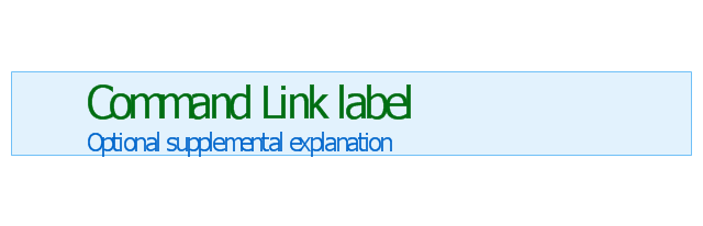
Command link - selected

Command link

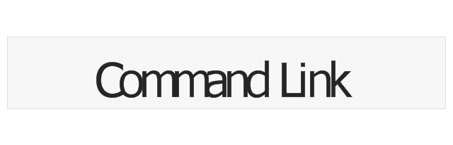
Command link
Command link 2
Drop-down button with text box
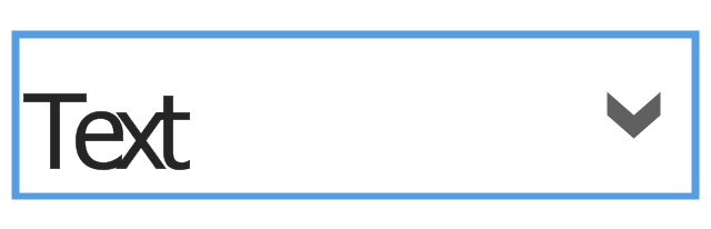
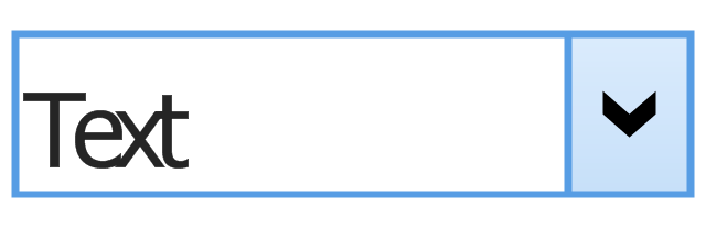
Drop-down button with text box - selected
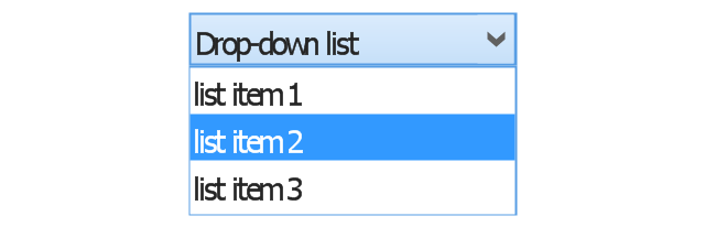
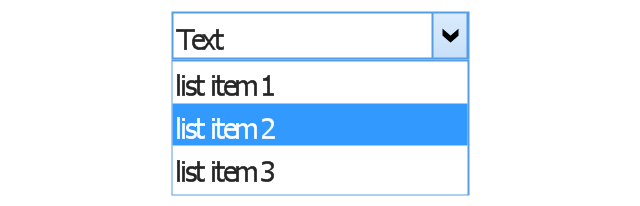
Drop-down list

List item

List item - selected

Drop-down button with text box 2
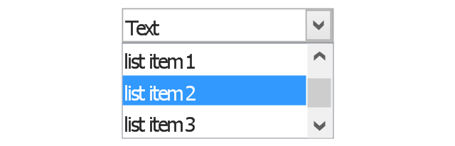
Drop-down list 2

Drop-down button
Drop-down button - selected
Combo box
Combo box 2
Combo box with scroller
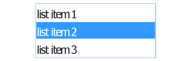
List box
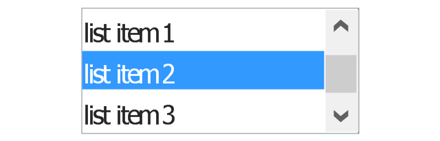
List box with scrollbar
List view
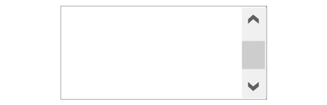
Vertical scroller

Horizontal scroller

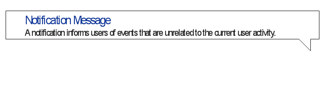
Notification
Options button

Close button

Text label

Progress bar

Search box

Search symbol

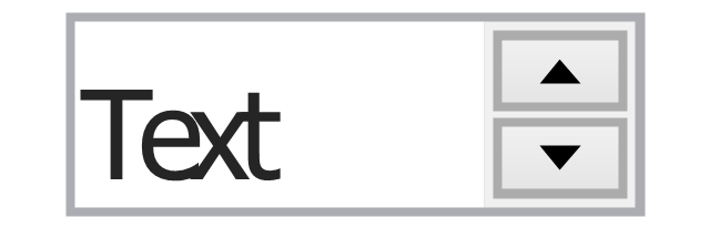
Spin control
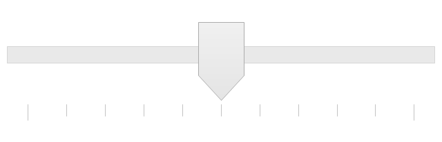
Slider - 5 intervals
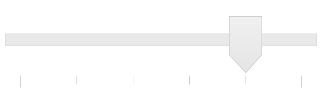
Slider - 10 intervals
Status bar

Start button

Status bar with Start button

Viewed window

Current window state

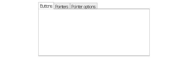
Tab control

Tab control - selected

Tab view page

Tab view
Text box
Text box label

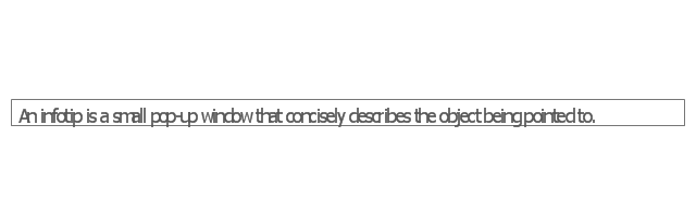
Tooltip

Infotip
Cisco Network Topology. Cisco icons, shapes, stencils and symbols
")
Cisco LAN. Cisco icons, shapes, stencils and symbols
")
Cisco Optical. Cisco icons, shapes, stencils and symbols
")
Electrical Symbols — Thermo

Electrical Symbols — Power Sources

Electrical Symbols — Stations

Process Flow Chart

The vector stencils library "Cisco network topology" contains 89 symbols of Cisco network devices and design elements for drawing computer network topology diagrams.
"There are two basic categories of network topologies:
(1) Physical topologies,
(2) Logical topologies.
The shape of the cabling layout used to link devices is called the physical topology of the network. This refers to the layout of cabling, the locations of nodes, and the interconnections between the nodes and the cabling. The physical topology of a network is determined by the capabilities of the network access devices and media, the level of control or fault tolerance desired, and the cost associated with cabling or telecommunications circuits.
The logical topology in contrast, is the way that the signals act on the network media, or the way that the data passes through the network from one device to the next without regard to the physical interconnection of the devices." [Network topology. Wikipedia]
The symbols example "Cisco network topology - Vector stencils library" was created using the ConceptDraw PRO diagramming and vector drawing software extended with the Cisco Network Diagrams solution from the Computer and Networks area of ConceptDraw Solution Park.
www.conceptdraw.com/ solution-park/ computer-networks-cisco
Router

Broadband router

Router firewall

Wireless router

Workgroup switch

ATM switch

ISDN switch

Multilayer switch

Protocol translator

Communications server

Transpath

Bridge

Terminal server

Route switch processor

Content engine (cache director)
-cisco-network-topology---vector-stencils-library.png--diagram-flowchart-example.png)
Management engine (ME 1100)
-cisco-network-topology---vector-stencils-library.png--diagram-flowchart-example.png)
Switch processor

ITP

Voice gateway

BBSM

ATA

SIP Proxy server

NetRanger

Cisco 1000

IP

System controller

ACE

Directory server

ADM

Cisco Unity Express

Unity server

Cisco security

CallManager

DSLAM

H.323

CDM (Content Distribution Manager)
-cisco-network-topology---vector-stencils-library.png--diagram-flowchart-example.png)
ICM

Access point

Wireless bridge

Wireless connectivity

Guard

Mobile access router

Carrier Routing System (CRS)
-cisco-network-topology---vector-stencils-library.png--diagram-flowchart-example.png)
Vault

Workstation

PC

Macintosh

Cloud, gold

Cloud, white

Cloud, standard color

Cisco security management

PBX

DPT

Government building

Headquarters, blue

Router in building

Man

Woman

Workgroup switch, subdued

Router, subdued

File server

Firewall, horizontal

Firewall, vertical

Firewall, vertical, subdued

Lock

Key

Lock and key

Car

Truck

File cabinet

Breakout box

Breakout box, blue

Host

Relational database

Modem

BBS (Bulletin Board System)
-cisco-network-topology---vector-stencils-library.png--diagram-flowchart-example.png)
Satellite

Satellite dish

UPS

RPS

MAU

PAD

PAD X.28

Diskette

Contact center

Page icon
Antenna

Antenna, blue

Radio tower

Local area network (LAN). Computer and Network Examples
. Computer and Network Examples")

Cross Functional Diagram

- Mechanical Drawing Symbols | Design elements - Fluid power ...
- Mechanical Drawing Symbols | Design elements - Pneumatic pumps ...
- Symbol Of Motor And Pump
- Mechanical Drawing Symbols | Mechanical Design Software ...
- Mechanical Drawing Symbols | Mechanical Drawing Software ...
- Mechanical Drawing Symbols | Pneumatic 5-ported 3-position valve ...
- Technical drawing - Machine parts assembling | Mechanical ...
- Pneumatic 5-ported 3-position valve template - Mac | Design ...
- Symbol Rotary Pump
- Motor
- Mechanical Drawing Symbols | Mechanical Engineering ...
- Cisco products additional - Vector stencils library | Logical symbols ...
- Mechanical Drawing Symbols | Design elements - Mechanics | CAD ...
- How to Create a Mechanical Diagram | Technical drawing - Machine ...
- Types And Symbols Of Pumps
- Mechanical Drawing Symbols | Mechanical Engineering ...
- Mechanical Drawing Symbols | Mechanical Engineering ...
- HVAC Plans | Block diagram - Automotive HVAC system | How to ...
- Mechanical Drawing Symbols | Mechanical Engineering ...
- Hydraulic 4-ported 3-position valve template - Win | Hydraulic ...