Electrical Symbols — Stations

Audio & Video Connector Types

Examples of Flowchart


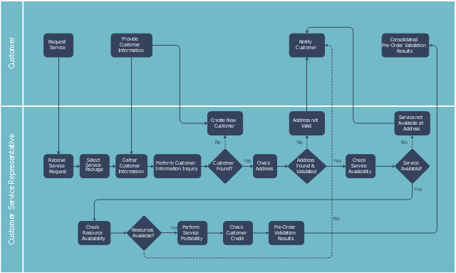
This swim lane diagram sample shows the telecom services process flow.
"Telecommunication is communication at a distance by technological means, particularly through electrical signals or electromagnetic waves. ...
Electrical and electromagnetic telecommunication technologies include telegraph, telephone, and teleprinter, networks, radio, microwave transmission, fiber optics, communications satellites and the Internet." [Telecommunication. Wikipedia]
"A telecommunications service provider or TSP is a type of communications service provider that has traditionally provided telephone and similar services. This category includes incumbent local exchange carriers, competitive local exchange carriers, and mobile wireless communication companies. ...
While some people use the terms "telecom service provider" and "communications service provider" interchangeably, the term TSP generally excludes Internet service providers (ISPs), cable companies, satellite TV, and managed service providers. ...
TSPs provide access to telephone and related communications services." [Telecommunications service provider. Wikipedia]
The cross-functional flowchart example "Providing telecom services" was created using the ConceptDraw PRO diagramming and vector drawing software extended with the Cross-Functional Flowcharts solution from the Business Processes area of ConceptDraw Solution Park.
Swin lane diagram
Electrical Symbols — Electron Tubes

Audio Connectors

 Electronic Block Diagrams
The Electronic Block Diagrams solution for ConceptDraw DIAGRAM includes a set of diagrams samples and a large number of specialized electronic and electrical symbols of electronic blocks, amplifiers, pulses, repeaters, converters, waveforms, electric filters, delay elements, etc. All symbols are highly simple and common for electronics. They allow designing strict and clear diagrams and electronics graphical designs for documentation, specifications, reports, presentation slides. Use them in electrical engineering, to design and construct electronic equipment, show sequence of pulses and flow of energy, and rapidly identify points of interest or trouble spots in electronic circuits.
What Is an Action Mind Map

The vector stencils library "Computers and network isometric" contains 56 3D clipart images of computer and network devices and equipment for drawing network diagrams.
The clip art example "Computers and network isometric - Vector stencils library" was created using the ConceptDraw PRO diagramming and vector drawing software extended with the Computer and Networks solution from the Computer and Networks area of ConceptDraw Solution Park.
The clip art example "Computers and network isometric - Vector stencils library" was created using the ConceptDraw PRO diagramming and vector drawing software extended with the Computer and Networks solution from the Computer and Networks area of ConceptDraw Solution Park.
Laptop

DDCS

Server

Webcam

Wireless Network Storage

Personal computer

VoIP phone

Fax

Plotter

Mobile phone

Feature phone

Printer

Satellite dish

Satellite antenna

Automatic-tracking satellite dish
Wireless access point

Wireless router

Router

Network switch

Network device

Mobile GPS Terminal

GPS phone

Television antenna

Radio tower

Base station

Satellite

In-vehicle satellite telecommunication

Satellite dishes on ship

Airplane

Internet

Man

Woman

Call-center

Honeycomb

Mountain

Radio waves

Radio waves

Tower block

Office building

House

House

Globe

Wireless security camera

Truck

Tree

Conifer tree

1U hub / switch

2U hub / switch

1U server

2U Server

3U Server

4U Server

Communications satellite

Car

Radio waves

Firewall

Mesh Network Topology Diagram

What is Electrical Engineering? Basic Electrical Engineering Software

Pipe Bender Plans

Electrical Symbols — Transmission Paths

Aerospace - Design Elements

The vector stencils library "Computers and network isometric" contains 56 3D clipart images of computer and network devices and equipment for drawing network diagrams.
The clip art example "Computers and network isometric - Vector stencils library" was created using the ConceptDraw PRO diagramming and vector drawing software extended with the Computer and Networks solution from the Computer and Networks area of ConceptDraw Solution Park.
The clip art example "Computers and network isometric - Vector stencils library" was created using the ConceptDraw PRO diagramming and vector drawing software extended with the Computer and Networks solution from the Computer and Networks area of ConceptDraw Solution Park.
Laptop
DDCS
Server
Webcam
Wireless Network Storage
Personal computer
VoIP phone
Fax
Plotter
Mobile phone
Feature phone
Printer
Satellite dish
Satellite antenna
Automatic-tracking satellite dish
Wireless access point
Wireless router
Router
Network switch
Network device
Mobile GPS Terminal
GPS phone
Television antenna
Radio tower
Base station
Satellite
In-vehicle satellite telecommunication
Satellite dishes on ship
Airplane
Internet
Man
Woman
Call-center
Honeycomb
Mountain
Radio waves
Radio waves
Tower block
Office building
House
House
Globe
Wireless security camera
Truck
Tree
Conifer tree
1U hub / switch
2U hub / switch
1U server
2U Server
3U Server
4U Server
Communications satellite
Car
Radio waves
Firewall
Metro Maps

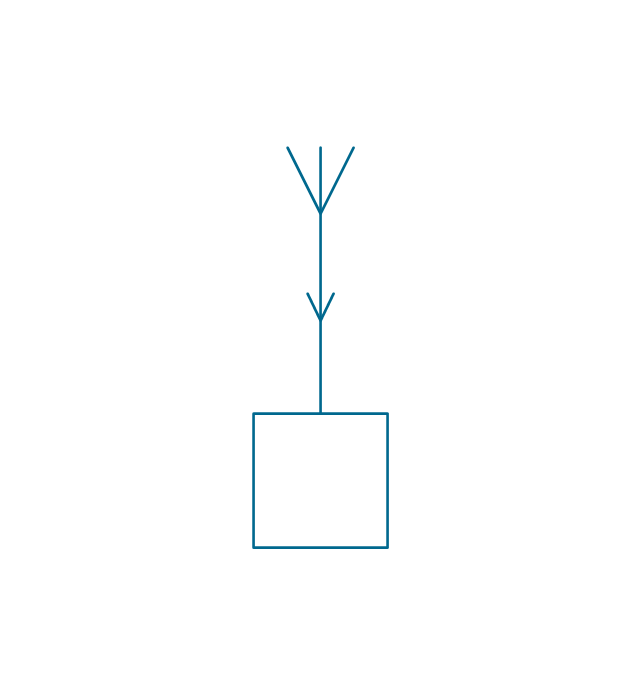
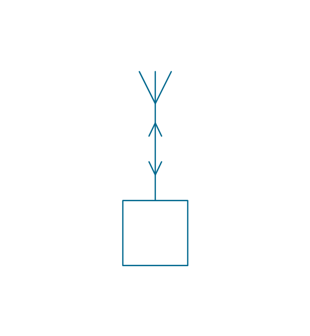
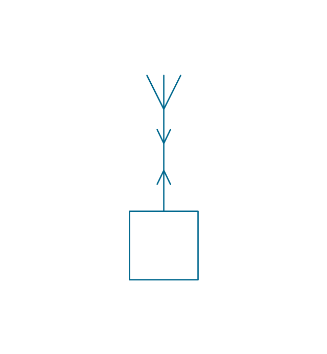
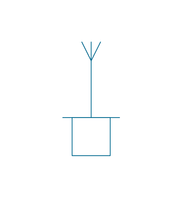
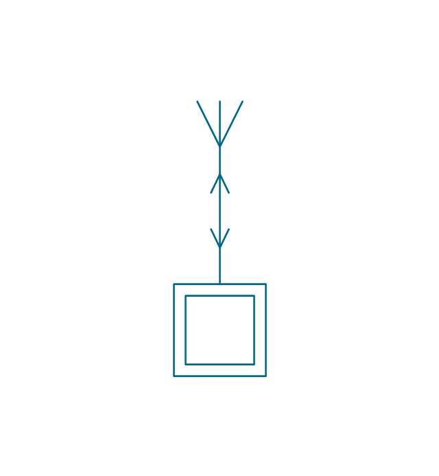
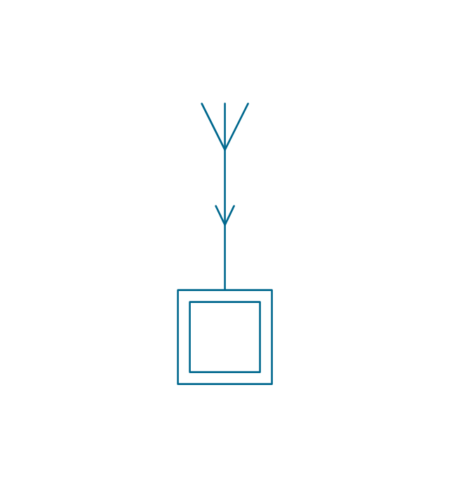
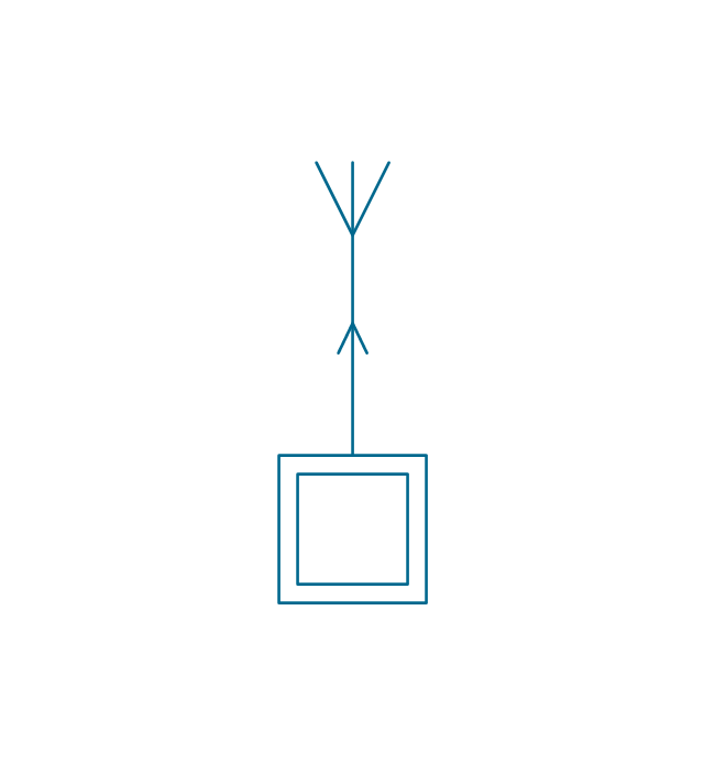
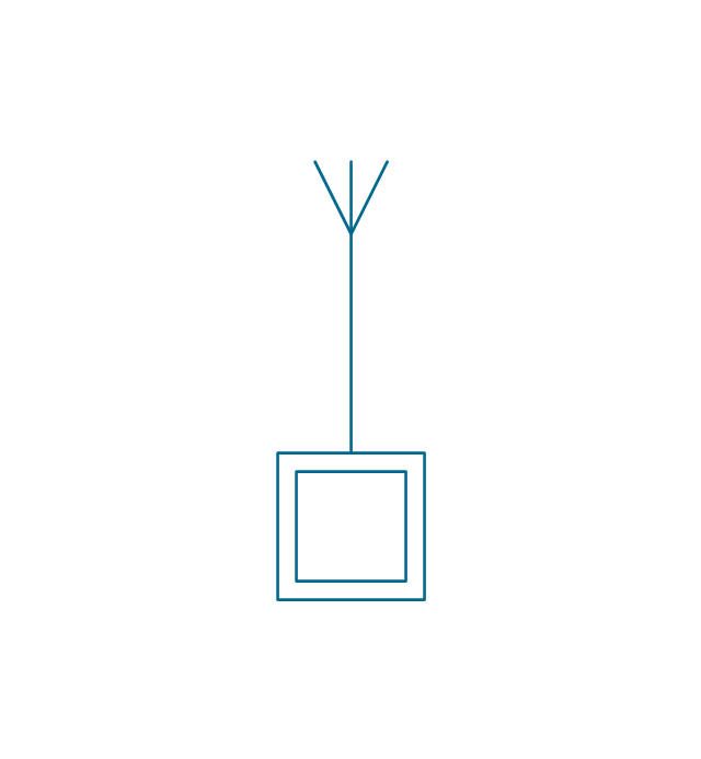
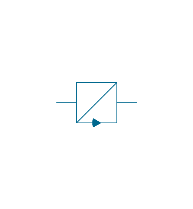
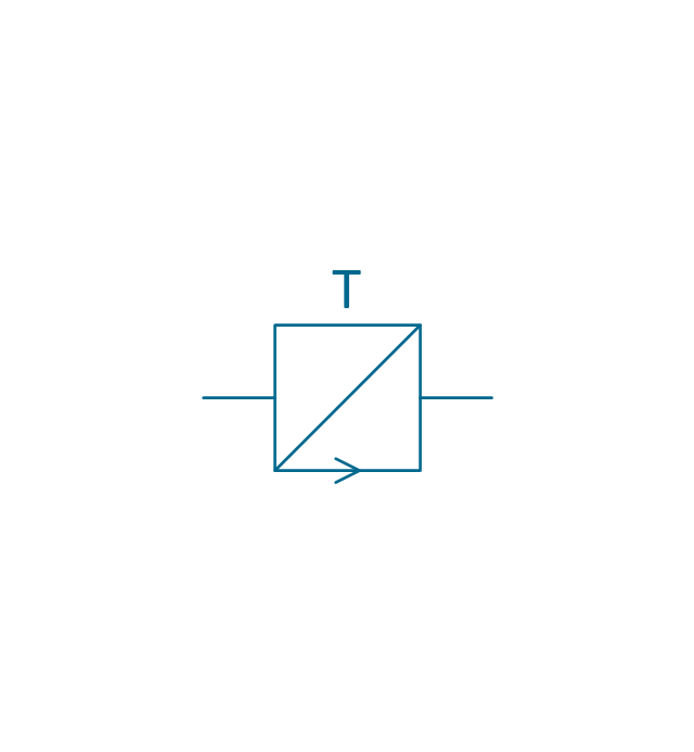
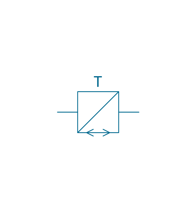
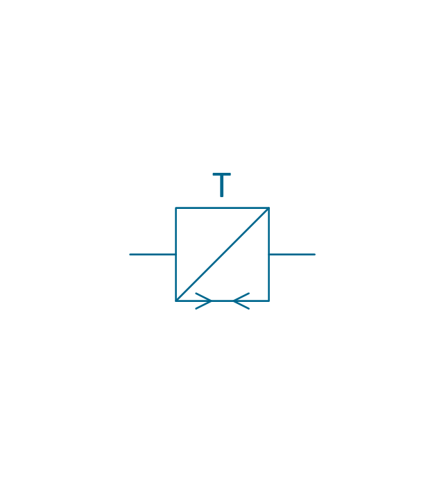
The vector stencils library "Stations" contains 110 symbols of communications equipment, generating, transmitting and receiving stations; substations; satellites; and power plants.
Use these shapes for drawing diagrams of power generation and distribution and radio relay systems in the ConceptDraw PRO diagramming and vector drawing software extended with the Electrical Engineering solution from the Engineering area of ConceptDraw Solution Park.
www.conceptdraw.com/ solution-park/ engineering-electrical
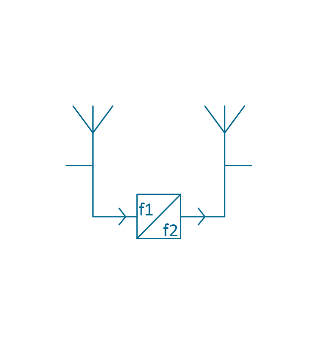
Radio relay station
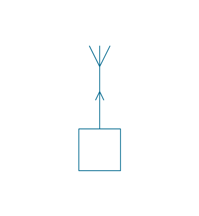
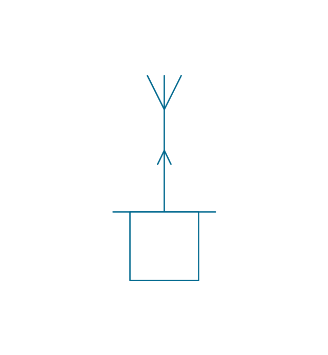
Transmission radio station
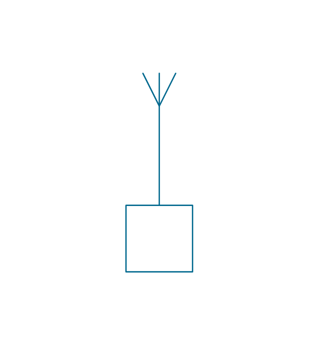
Radio station
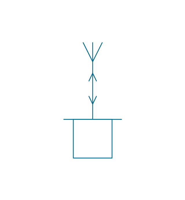
Reception radio station
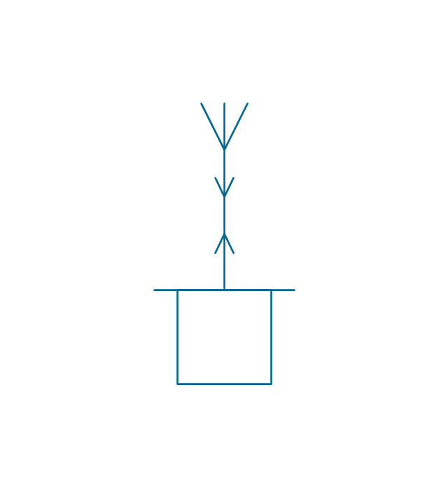
Alternating radio station
Simultaneous radio station
End radio station

End radio station 2

General radio station

General radio station 2

Repeater radio station

Repeater radio station 2

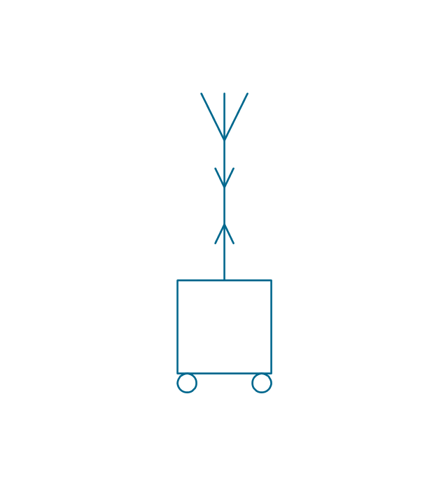
Portable station
Transmission portable station
Reception portable station

Alternating portable station
Simultaneous portable station
Mobile simultaneous station
Mobile alternating station

Mobile reception station
Mobile transmission station
Mobile station

Direction finding station
Radio beacon station
Simultaneous controlling station
Alternating controlling station
Reception controlling station
Transmission controlling station
Controlling station
End station

Repeater station

Subscriber equipment

Subscriber equipment 2

Passive relay

Active space station

Passive space station

Space station

Earth tracking station
Earth communication service

Telegraph repeater, one-way simplex
Telegraph repeater, two-way simplex

Telegraph repeater, duplex

Telegraph repeater, one-way simplex 2
Telegraph repeater, two-way simplex 2
Telegraph repeater, duplex 2
Telegraph repeater qualifiers, polar direct-current (double current)
-stations---vector-stencils-library.png--diagram-flowchart-example.png)
Telegraph repeater qualifier, neutral direct-current (single current) +/o
-+/o-stations---vector-stencils-library.png--diagram-flowchart-example.png)
Telegraph repeater qualifier, neutral direct-current (single current) -/o
--/o-stations---vector-stencils-library.png--diagram-flowchart-example.png)
Telegraph equipment

Telegraph transmitter

Telegraph receiver

Two-way simplex telegraph

Duplex telegraph

Telegraph transmitter 2

Telegraph receiver 2

Two-way simplex telegraph 2

Duplex telegraph 2

Telegraph equipment qualifier, tape printing

Telegraph equipment qualifier, tape perforating

Telegraph equipment qualifier, tape printing/perforating

Telegraph equipment qualifier, page printing

Telegraph equipment qualifier, keyboard

Telegraph equipment qualifier, facsimile

Telephone

Dial telephone

Push-button telephone

Multiple lines telephone

Coin box telephone

Speaker phone

Amplified phone

Generating station (in service)
-stations---vector-stencils-library.png--diagram-flowchart-example.png)
Generating station (planned)
-stations---vector-stencils-library.png--diagram-flowchart-example.png)
Electric heat station (in service)
-stations---vector-stencils-library.png--diagram-flowchart-example.png)
Electric heat station (planned)
-stations---vector-stencils-library.png--diagram-flowchart-example.png)
Hydroelectric station (planned)
-stations---vector-stencils-library.png--diagram-flowchart-example.png)
Hydroelectric station (in service)
-stations---vector-stencils-library.png--diagram-flowchart-example.png)
Hydroelectric station (planned) 2
-2-stations---vector-stencils-library.png--diagram-flowchart-example.png)
Hydroelectric station (in service) 2
-2-stations---vector-stencils-library.png--diagram-flowchart-example.png)
Hydroelectric station (planned) 3
-3-stations---vector-stencils-library.png--diagram-flowchart-example.png)
Hydroelectric station (in service) 3
-3-stations---vector-stencils-library.png--diagram-flowchart-example.png)
Hydroelectric station (planned) 4
-4-stations---vector-stencils-library.png--diagram-flowchart-example.png)
Hydroelectric station (in service) 4
-4-stations---vector-stencils-library.png--diagram-flowchart-example.png)
Thermoelectric station (planned)
-stations---vector-stencils-library.png--diagram-flowchart-example.png)
Thermoelectric station (in service)
-stations---vector-stencils-library.png--diagram-flowchart-example.png)
Coal fueled station (planned)
-stations---vector-stencils-library.png--diagram-flowchart-example.png)
Coal fueled station (in service)
-stations---vector-stencils-library.png--diagram-flowchart-example.png)
Oil/gas fueled station (planned)
-stations---vector-stencils-library.png--diagram-flowchart-example.png)
Oil/gas fueled station (in service)
-stations---vector-stencils-library.png--diagram-flowchart-example.png)
Nuclear station (planned)
-stations---vector-stencils-library.png--diagram-flowchart-example.png)
Nuclear station (in service)
-stations---vector-stencils-library.png--diagram-flowchart-example.png)
Geothermic station (planned)
-stations---vector-stencils-library.png--diagram-flowchart-example.png)
Geothermic station (in service)
-stations---vector-stencils-library.png--diagram-flowchart-example.png)
Solar station (planned)
-stations---vector-stencils-library.png--diagram-flowchart-example.png)
Solar station (in service)
-stations---vector-stencils-library.png--diagram-flowchart-example.png)
Wind station (planned)
-stations---vector-stencils-library.png--diagram-flowchart-example.png)
Wind station (in service)
-stations---vector-stencils-library.png--diagram-flowchart-example.png)
Converting substation (in service)
-stations---vector-stencils-library.png--diagram-flowchart-example.png)
Converting substation (planned)
-stations---vector-stencils-library.png--diagram-flowchart-example.png)
Substation (planned)
-stations---vector-stencils-library.png--diagram-flowchart-example.png)
Substation (in service)
-stations---vector-stencils-library.png--diagram-flowchart-example.png)
Prime mover, reciprocating engine

Prime mover, gas turbine

Converting station

Converting station 2

Switching station

Switching station 2

Rectifier substation (planned)
-stations---vector-stencils-library.png--diagram-flowchart-example.png)
Rectifier substation (in service)
-stations---vector-stencils-library.png--diagram-flowchart-example.png)
Plasma station MHD (planned)
-stations---vector-stencils-library.png--diagram-flowchart-example.png)
Plasma station MHD (in service)
-stations---vector-stencils-library.png--diagram-flowchart-example.png)
 Telecommunication Network Diagrams
Telecommunication Network Diagrams solution extends ConceptDraw DIAGRAM software with samples, templates, and great collection of vector stencils to help the specialists in a field of networks and telecommunications, as well as other users to create Computer systems networking and Telecommunication network diagrams for various fields, to organize the work of call centers, to design the GPRS networks and GPS navigational systems, mobile, satellite and hybrid communication networks, to construct the mobile TV networks and wireless broadband networks.
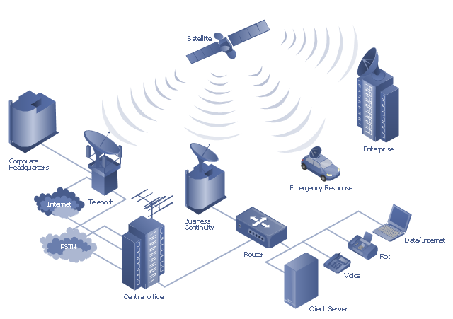
"A communications satellite or comsat is an artificial satellite sent to space for the purpose of telecommunications. Modern communications satellites use a variety of orbits including geostationary orbits, Molniya orbits, elliptical orbits and low (polar and non-polar) Earth orbits.
For fixed (point-to-point) services, communications satellites provide a microwave radio relay technology complementary to that of communication cables. They are also used for mobile applications such as communications to ships, vehicles, planes and hand-held terminals, and for TV and radio broadcasting." [Communications satellite. Wikipedia]
"Satellite telecommunication services:
Satellite crop monitoring,
Satellite Internet access,
Satellite navigation,
Satellite phone,
Satellite radio,
Satellite television." [Satellite. Wikipedia]
This hybrid satellite and common carrier network diagram example was created using the ConceptDraw PRO diagramming and vector drawing software extended with the Telecommunication Network Diagrams solution from the Computer and Networks area of ConceptDraw Solution Park.
Satellite network diagram
Integrated Circuit

- Telecommunication Network Diagrams | Hybrid satellite and ...
- Social Media Flowchart Symbols | Radio networks. Computer and ...
- Computer and Networks Area | Radio Telescope Server Computer ...
- Aerospace - Vector stencils library | Radio Station Flowchart
- Providing telecom services | Flow Chart Of Radio Transmission
- Providing telecom services | Radio Communication Flow Chart
- Near field communication (NFC). Computer and Network Examples ...
- Telecommunication Network Diagrams | Flow Chart Of Radio Station
- Electrical Symbols — VHF UHF SHF | Basic Flowchart Symbols and ...
- Telecommunication Network Diagrams | Diagrams Of Radio Station