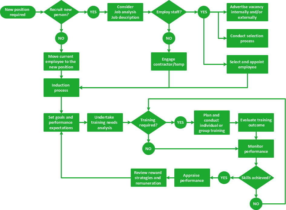
Workflow Diagram Software
Workflow Diagram
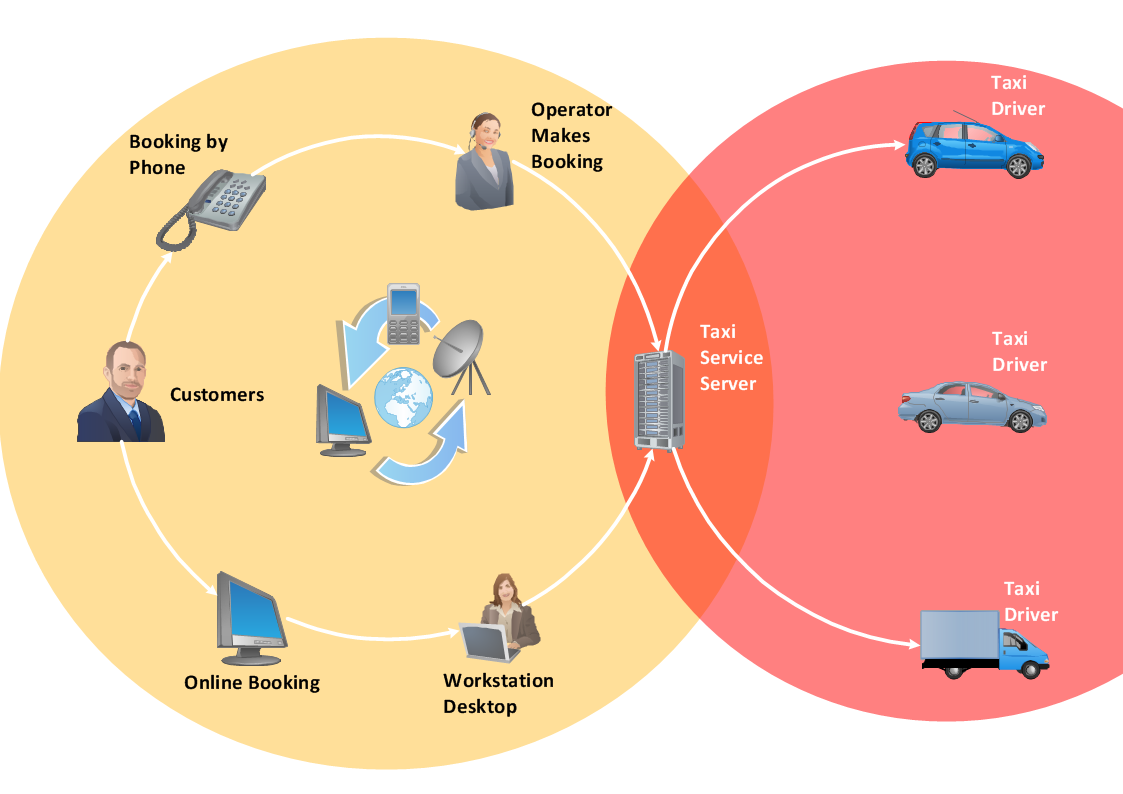
UML Use Case Diagram Example - Taxi Service

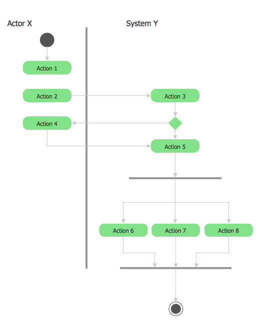
UML 2 4 Process Flow Diagram
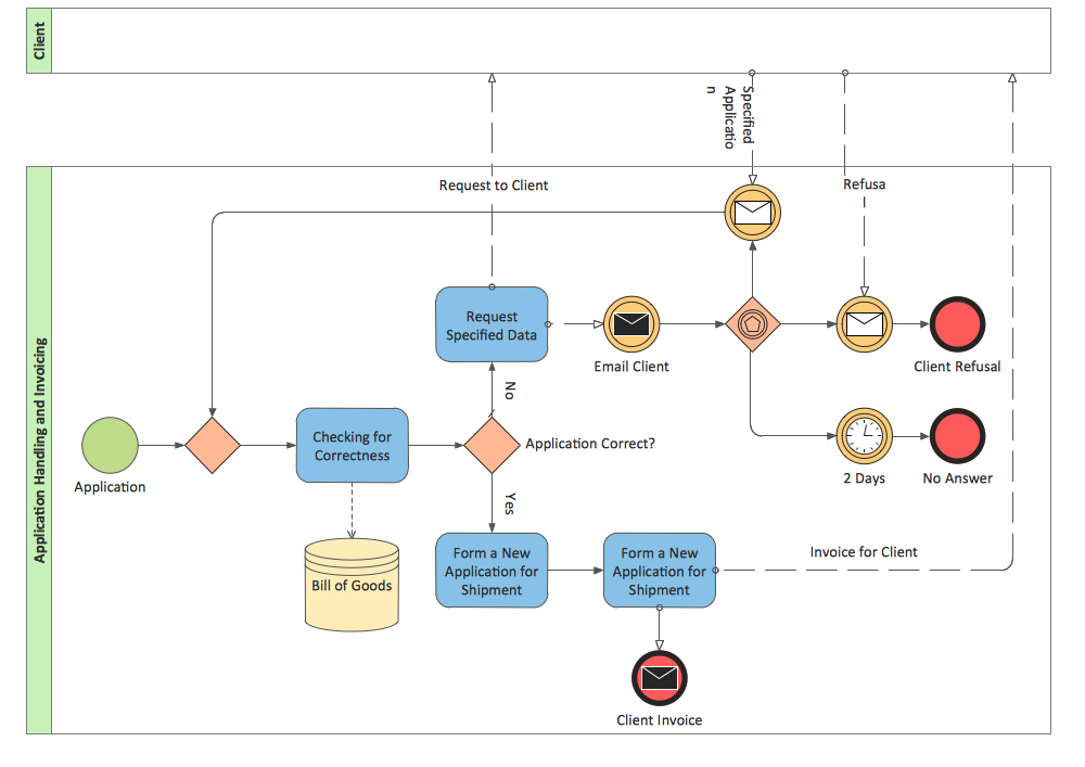
BPMN 2.0
Diagramming Software for UML Composite Structure Diagrams


TQM Software — Build Professional TQM Diagrams
IDEF3 Standard

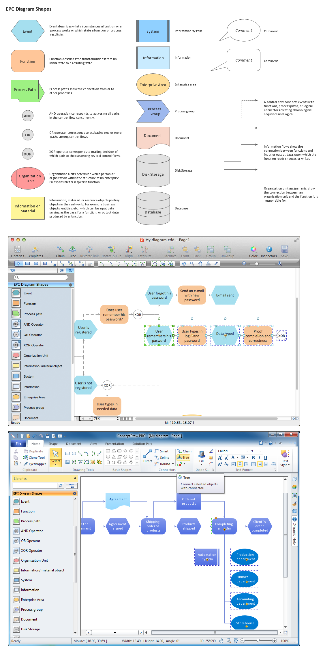
The Building Blocks Used in EPC Diagrams
Total Quality Management Definition

UML Diagram Types List

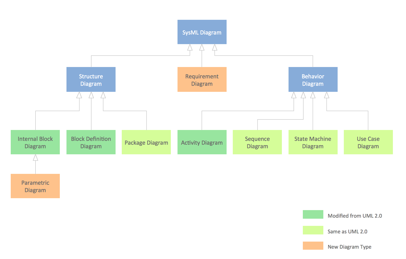
SysML Diagram
Model Based Systems Engineering

ConceptDraw Arrows10 Technology
UML Class Diagram Notation

- Taxi Service Data Flow Diagram DFD Example | Taxi order process ...
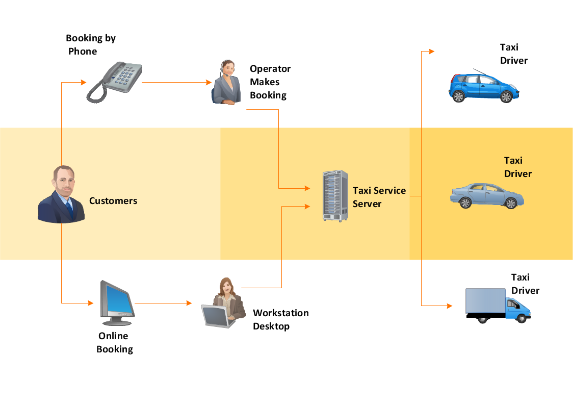
- Cab booking public process - Collaboration BPMN 2.0 diagram ...
- Process Flowchart | Taxi Service Data Flow Diagram DFD Example ...
- Block diagram - Gap model of service quality | Taxi Service Data ...
- Process Flowchart | Taxi Service Data Flow Diagram DFD Example ...
- Taxi service order procedure - BPMN 1.2 diagram | Taxi Service ...
- UML Use Case Diagram Example - Taxi Service | Diagramming ...
- Business Process Diagrams | Types of Flowchart - Overview ...
- Taxi Service
- UML Use Case Diagram Example - Taxi Service | Business Process ...
- Workflow Diagram Software | Taxi Service Data Flow Diagram DFD ...
- UML Use Case Diagram Example - Taxi Service | Taxi service order ...
- Business Process Diagrams | UML Use Case Diagram Example ...
- Taxi Service Data Flow Diagram DFD Example | UML Use Case ...
- UML Use Case Diagram Example - Taxi Service | Process Flowchart ...
- Taxi Service Data Flow Diagram DFD Example | Workflow Diagram ...
- Process Flowchart | Copying Service Process Flowchart. Flowchart ...
- UML Use Case Diagram Example - Taxi Service
- UML Use Case Diagram Example - Taxi Service | Software Diagram ...
- Flowchart Software | UML Use Case Diagram Example - Taxi ...