Piping and Instrumentation Diagram Software

Electrical Symbols — Stations

Interior Design. Piping Plan — Design Elements

Mechanical Drawing Symbols

Technical Drawing Software

 Chemical and Process Engineering
This chemical engineering solution extends ConceptDraw DIAGRAM.9.5 (or later) with process flow diagram symbols, samples, process diagrams templates and libraries of design elements for creating process and instrumentation diagrams, block flow diagrams (BFD
Building Drawing. Design Element: Piping Plan


Process Flow Diagram Symbols

How To Make a Floor Plan

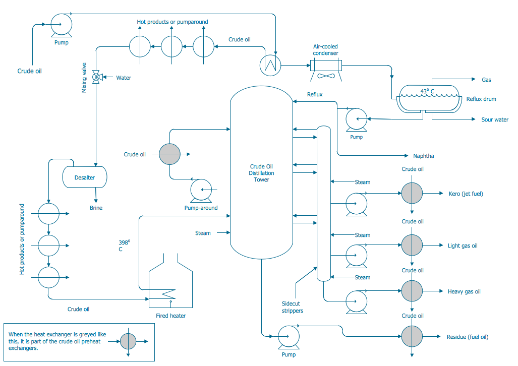
Process and Instrumentation Diagram
- Piping And Instrument Diagram Symbol Pipefitter Pdf
- Piping And Instrumentation Diagram Symbols Pdf
- Piping And Instrument Diagram Symbols
- Mass Flow Meter Symbol In Piping And Instrumentation Diagram
- Industrial Instrument Symbol In Pdf
- Process Flow Diagram Symbols | Piping and Instrumentation ...
- Instrumentation Valves Drawing Symbols Pdf
- Mechanical Drawing Symbols | Process Flow Diagram Symbols ...
- Piping And Instrumentation Diagram For Distillation Column
- Electrical Instrumentation Symbols