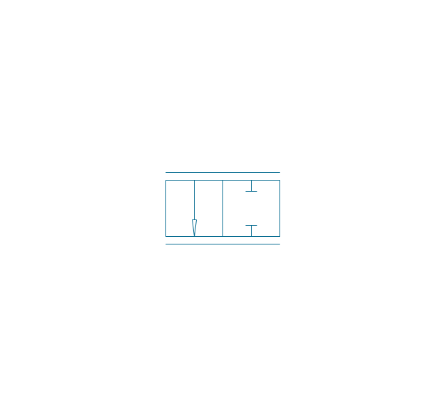
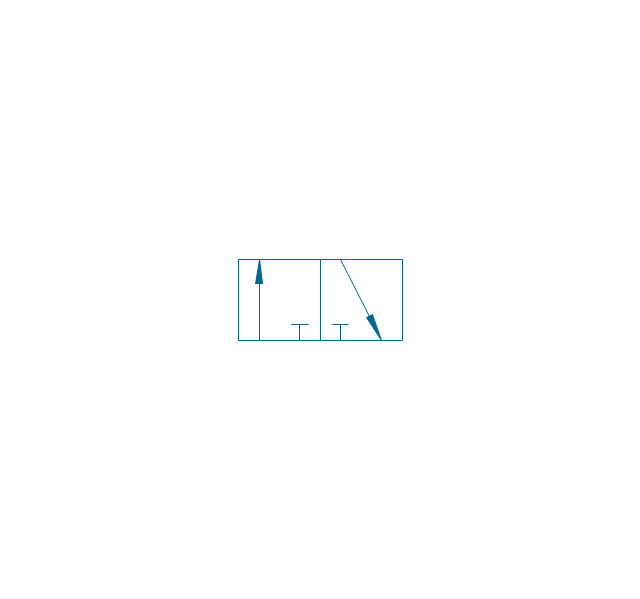
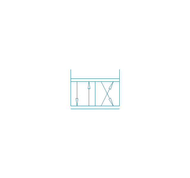
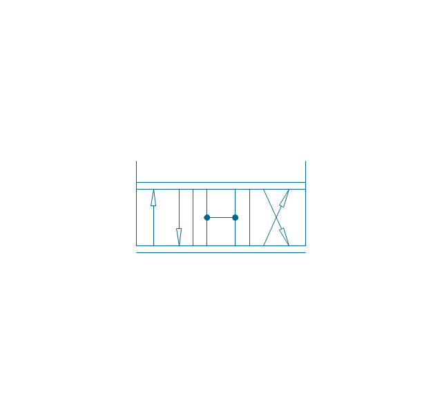
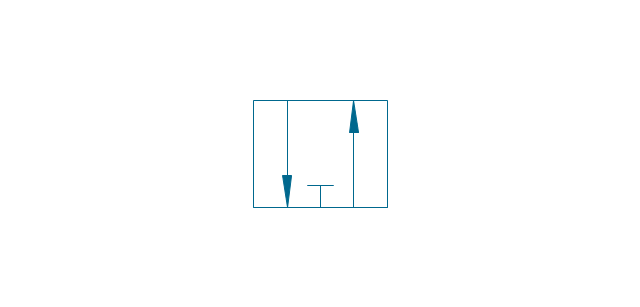
"Directional control valves are one of the most fundamental parts in hydraulic machinery as well and pneumatic machinery. They allow fluid flow into different paths from one or more sources. They usually consist of a spool inside a cylinder which is mechanically or electrically controlled. The movement of the spool restricts or permits the flow, thus it controls the fluid flow. ...
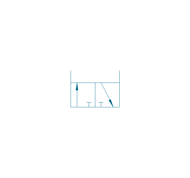
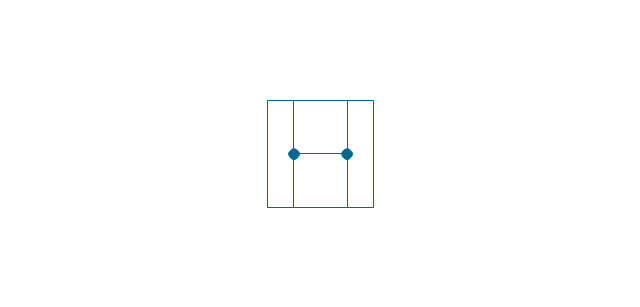
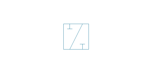
While working with layouts of hydraulic machinery it is cumbersome to draw actual picture of every valve and other components.instead of pictures symbols are used for variety of components in the hydraulic system to highlight the functional aspects. symbol for directional control valve is made of number of square boxes adjacent to each other depending on the number of positions.connections to the valve are shown on these squares by capital letters.usually they are named only in their normal position and not repeated in other positions.actuation system of the valve is also designated in its symbol." [Directional control valve. Wikipedia]
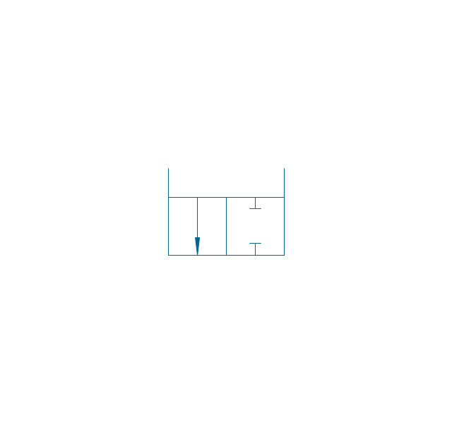
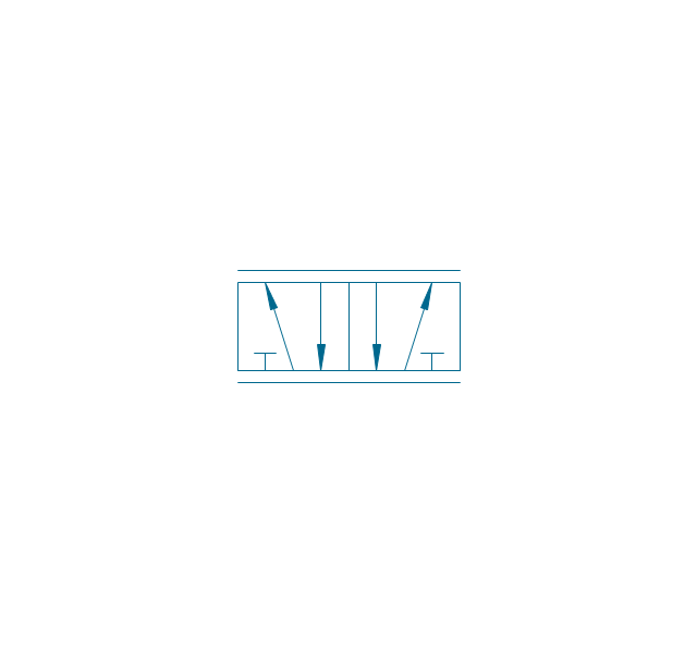
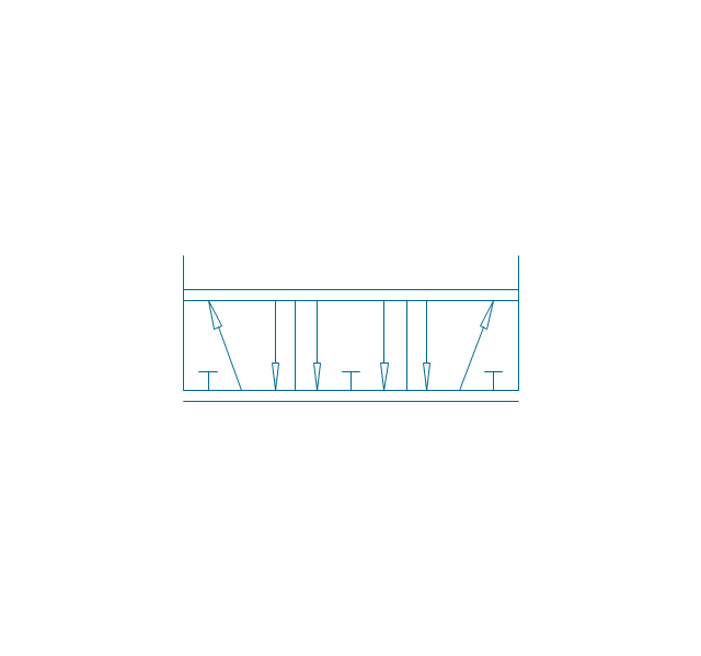
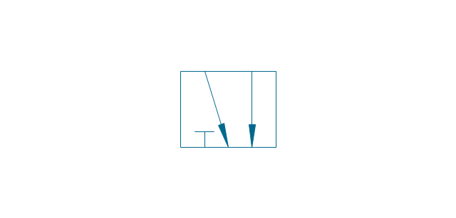
The Mac template "Pneumatic 5-ported 3-position valve" for the ConceptDraw PRO diagramming and vector drawing software is included in the Mechanical Engineering solution from the Engineering area of ConceptDraw Solution Park.
www.conceptdraw.com/ solution-park/ engineering-mechanical
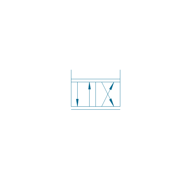
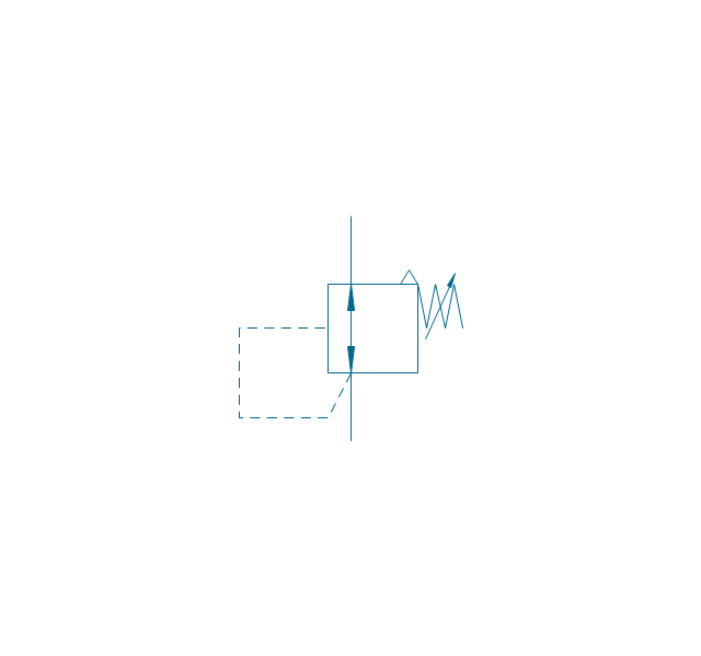
While working with layouts of hydraulic machinery it is cumbersome to draw actual picture of every valve and other components.instead of pictures symbols are used for variety of components in the hydraulic system to highlight the functional aspects. symbol for directional control valve is made of number of square boxes adjacent to each other depending on the number of positions.connections to the valve are shown on these squares by capital letters.usually they are named only in their normal position and not repeated in other positions.actuation system of the valve is also designated in its symbol." [Directional control valve. Wikipedia]
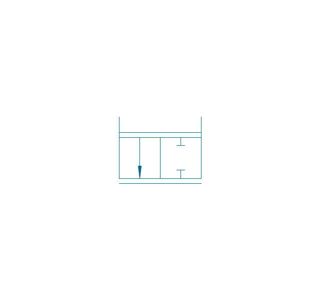
The Mac template "Pneumatic 5-ported 3-position valve" for the ConceptDraw PRO diagramming and vector drawing software is included in the Mechanical Engineering solution from the Engineering area of ConceptDraw Solution Park.
www.conceptdraw.com/ solution-park/ engineering-mechanical
Pneumatic directional control valve

The vector stencils library "Valve assembly" contains 141 symbols of pressure and flow regulators, flow direction indicators, controls, and symbols to design flow paths of control valves.
Use these valve assembly shapes to design the engineering drawings of hydraulic and pneumatic valve assemblies in fluid power systems.
"Control valves are valves used to control conditions such as flow, pressure, temperature, and liquid level by fully or partially opening or closing in response to signals received from controllers that compare a "setpoint" to a "process variable" whose value is provided by sensors that monitor changes in such conditions.
The opening or closing of control valves is usually done automatically by electrical, hydraulic or pneumatic actuators. Positioners are used to control the opening or closing of the actuator based on electric, or pneumatic signals.
A control valve consists of three main parts in which each part exist in several types and designs: Valve's actuator, Valve's positioner, Valve's body.
" [Control valves. Wikipedia]
The shapes example "" was created using the ConceptDraw PRO diagramming and vector drawing software extended with the Mechanical Engineering solution from the Engineering area of ConceptDraw Solution Park.
Valve assembly symbols

The vector stencils library "Fluid power valves" contains 93 symbols of pre-made hydraulic and pneumatic valves, including directional control valves, flow control valves, pressure control valves, and electrohydraulic and electropneumatic valves.
Use these shapes to design fluid power diagrams in the ConceptDraw PRO diagramming and vector drawing software extended with the Mechanical Engineering solution from the Engineering area of ConceptDraw Solution Park.
www.conceptdraw.com/ solution-park/ engineering-mechanical
Use these shapes to design fluid power diagrams in the ConceptDraw PRO diagramming and vector drawing software extended with the Mechanical Engineering solution from the Engineering area of ConceptDraw Solution Park.
www.conceptdraw.com/ solution-park/ engineering-mechanical
2/2 valve, pneum., finite positions

2/2 valve, pneum., infinite positions
2/2 valve, pneum., ext., fin. pos.
2/2 valve, pneum., ext., infin. pos.
2/2 valve, hydr., finite positions
2/2 valve, hydr., infinite positions

2/2 valve, hydr., ext., fin. pos.
2/2 valve, hydr., ext., infin. pos.
3/2 valve, pneum., finite positions
3/2 valve, pneum., infinite positions
3/2 valve, pneum., ext., fin. pos.
3/2 valve, pneum., ext., infin. pos.
3/2 valve, hydr., finite positions
3/2 valve, hydr., infinite positions
3/2 valve, hydr., ext., fin. pos.
3/2 valve, hydr., ext., infin. pos.
4/2 valve, pneum., finite positions

4/2 valve, pneum., infinite positions
4/2 valve, pneum., ext., fin. pos.
4/2 valve, pneum., ext., infin. pos.
4/2 valve, hydr., finite positions

4/2 valve, hydr., infinite positions

4/2 valve, hydr., ext., fin. pos.

4/2 valve, hydr., ext., infin. pos.
5/2 valve, pneum., finite positions
5/2 valve, pneum., infinite positions
5/2 valve, pneum., ext., fin. pos.

5/2 valve, pneum., ext., infin. pos.

5/2 valve, hydr., finite positions

5/2 valve, hydr., infinite positions
5/2 valve, hydr., ext., fin. pos.
5/2 valve, hydr., ext., infin. pos.
4/3 valve, pneum., finite positions

4/3 valve, pneum., infinite positions
4/3 valve, pneum., ext., fin. pos.

4/3 valve, pneum., ext., infin. pos.
4/3 valve, hydr., finite positions

4/3 valve, hydr., infinite positions

4/3 valve, hydr., ext., fin. pos.

4/3 valve, hydr., ext., infin. pos.

5/3 valve, pneum., finite positions
5/3 valve, pneum., infinite positions
5/3 valve, pneum., ext., fin. pos.
5/3 valve, pneum., ext., infin. pos.
5/3 valve, hydr., finite positions
5/3 valve, hydr., infinite positions
5/3 valve, hydr., ext., fin. pos.
5/3 valve, hydr., ext., infin. pos.
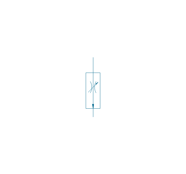
Restrictor valve

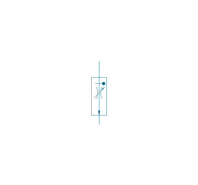
Restrictor valve, adjustable
Gate-valve, norm. open
Gate-valve, norm. open, adj.
Gate-valve, norm. closed

Gate-valve, norm. closed, adj.

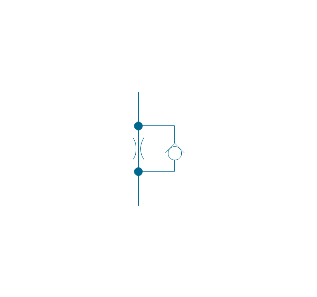
One-way restrictor
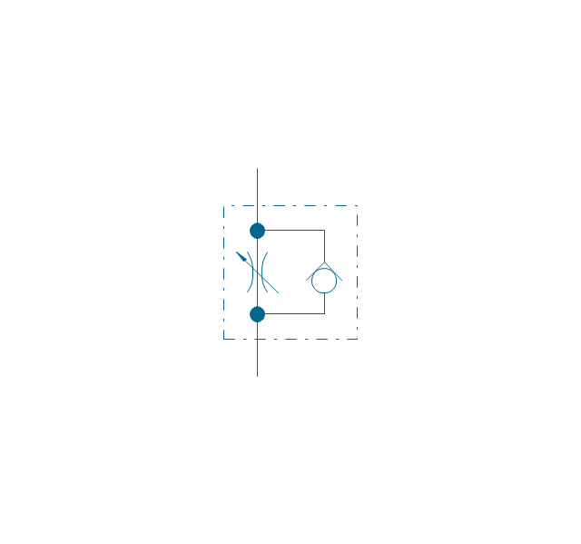
One-way restrictor, enclosed
Flow control, series flow
Flow control, temperature compensated
Flow control, bypass flow
Flow divider
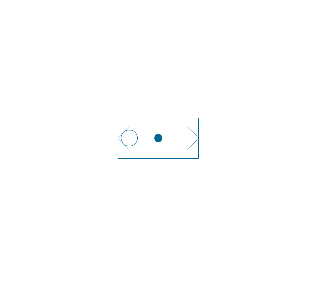
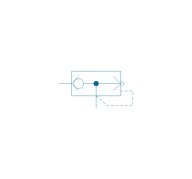
Non-return, pilot controlled
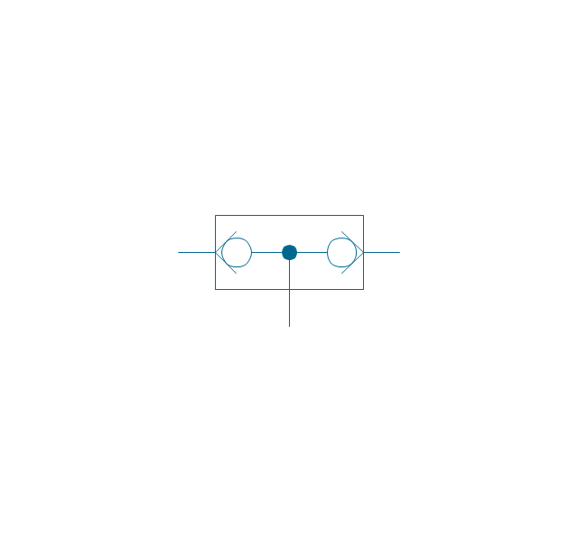
Non-return, pilot contr., spring
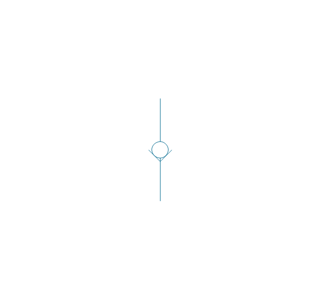
Non-return, free
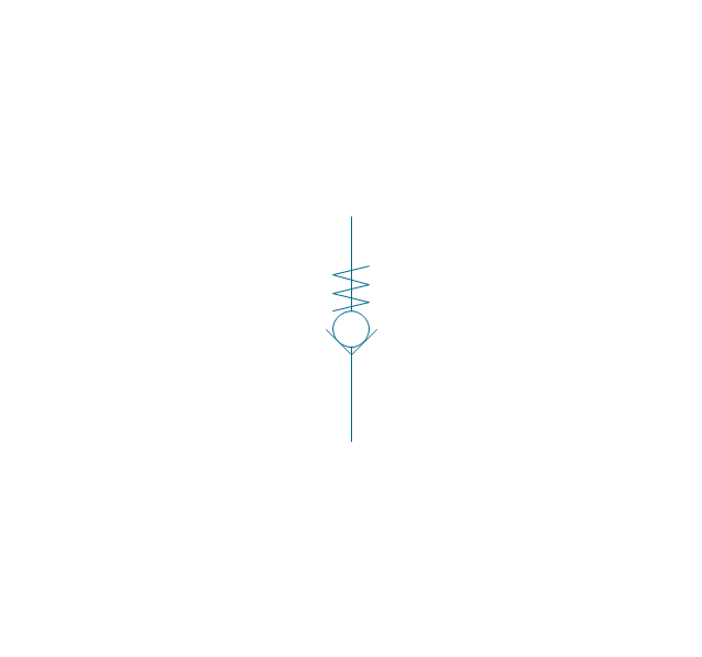
Non-return, spring loaded
Coupling (connect.), 1 valve
,-1-valve-fluid-power-valves---vector-stencils-library.png--diagram-flowchart-example.png)
Coupling (connect.), both valves
,-both-valves-fluid-power-valves---vector-stencils-library.png--diagram-flowchart-example.png)
Coupling (connect.), no valves
,-no-valves-fluid-power-valves---vector-stencils-library.png--diagram-flowchart-example.png)
Coupling (connect.), 1 valve, encl.
,-1-valve,-encl.-fluid-power-valves---vector-stencils-library.png--diagram-flowchart-example.png)
Coupling (connect.), both valves, encl.
,-both-valves,-encl.-fluid-power-valves---vector-stencils-library.png--diagram-flowchart-example.png)
Coupling (connect.), no valves, encl.
,-no-valves,-encl.-fluid-power-valves---vector-stencils-library.png--diagram-flowchart-example.png)
Coupling (discon.), 1 valve
,-1-valve-fluid-power-valves---vector-stencils-library.png--diagram-flowchart-example.png)
Coupling (discon.), both valves
,-both-valves-fluid-power-valves---vector-stencils-library.png--diagram-flowchart-example.png)
Coupling (discon.), no valves
,-no-valves-fluid-power-valves---vector-stencils-library.png--diagram-flowchart-example.png)
Coupling (discon.), 1 valve, encl.
,-1-valve,-encl.-fluid-power-valves---vector-stencils-library.png--diagram-flowchart-example.png)
Coupling (discon.), both valves, encl.
,-both-valves,-encl.-fluid-power-valves---vector-stencils-library.png--diagram-flowchart-example.png)
Coupling (discon.), no valves, encl.
,-no-valves,-encl.-fluid-power-valves---vector-stencils-library.png--diagram-flowchart-example.png)
Shuttle valve
Priority shuttle valve
Quick exhaust
Cartridge valve
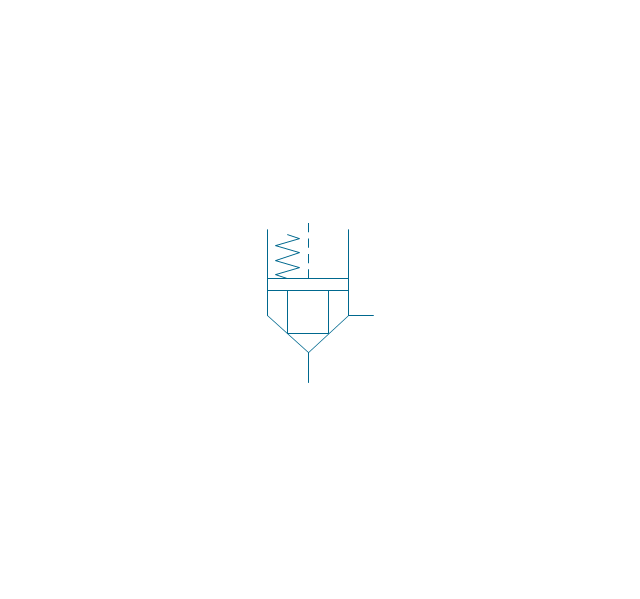
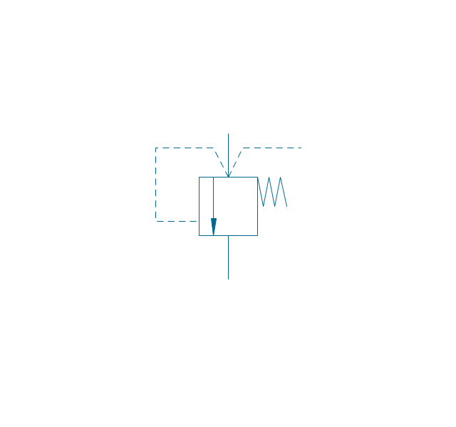
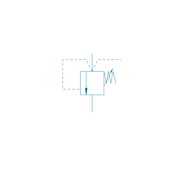
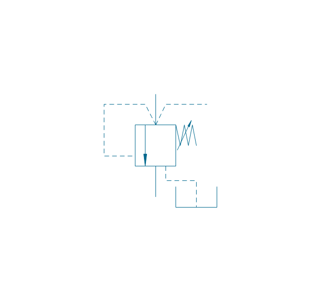
Pressure relief
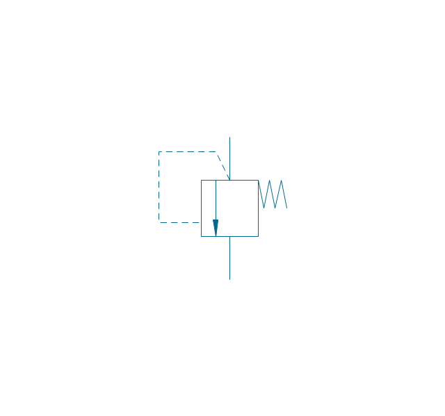
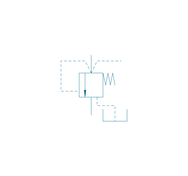
Pressure relief, drain
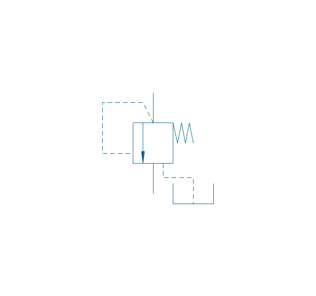
Pressure relief, vent port
Pressure relief, drain, vent port
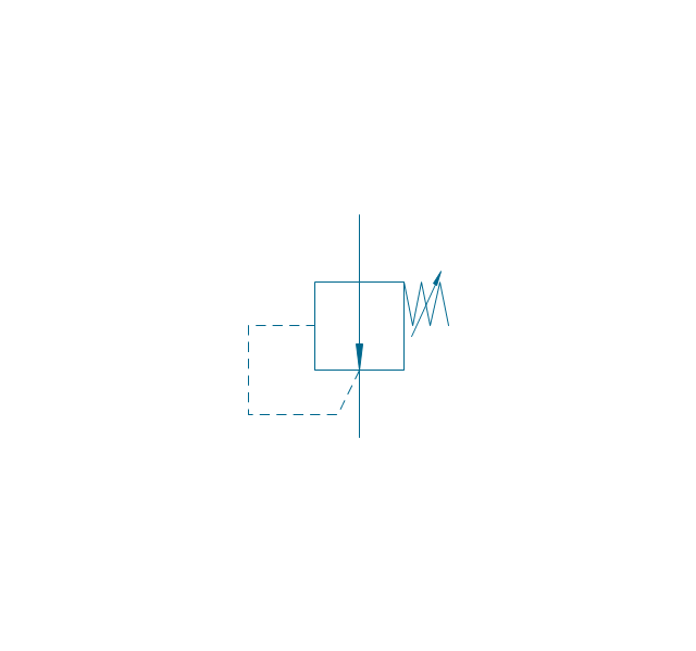
Pressure relief, var.
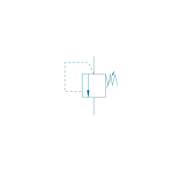
Pressure relief, var., drain
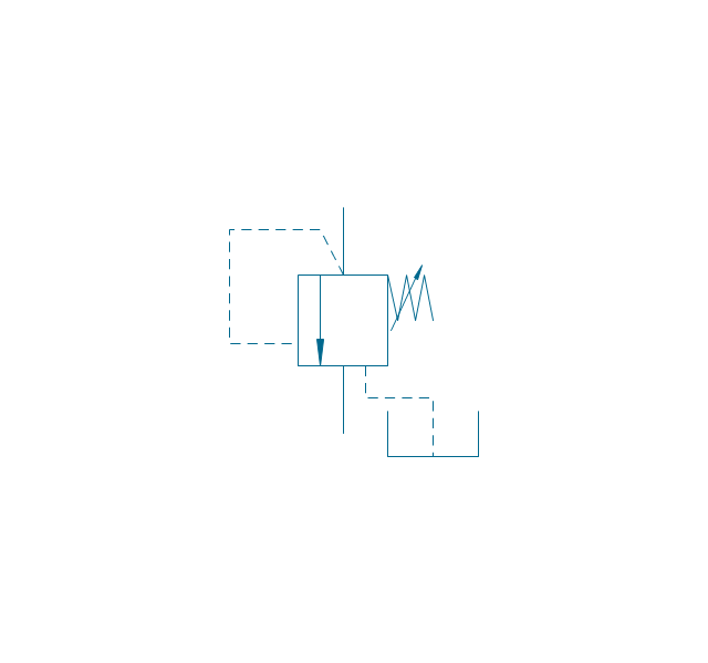
Pressure relief, var., vent port
Pressure relief, var., drain, vent port
Pressure relief 2
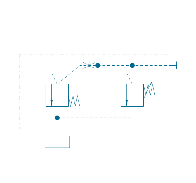
Pressure reducing, 1 stage
Pressure reducing, 2 stage
Pressure reducing, relief
Pressure relief (E)
-fluid-power-valves---vector-stencils-library.png--diagram-flowchart-example.png)
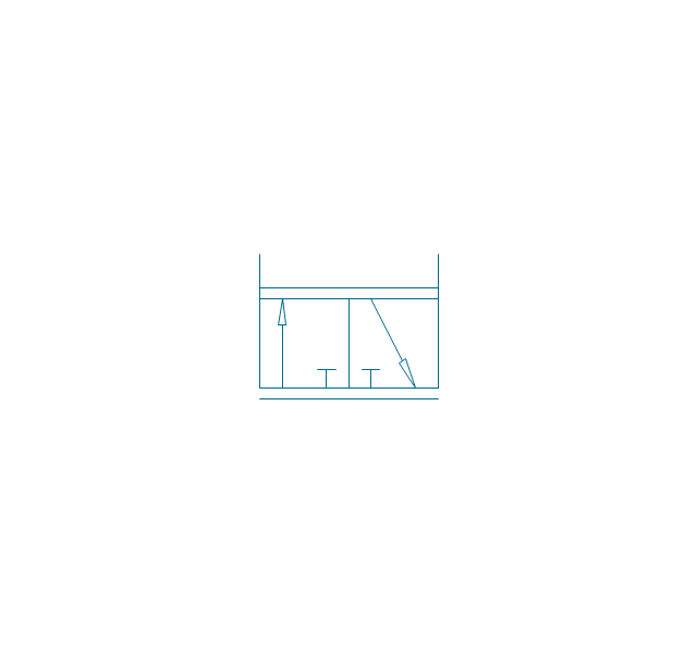
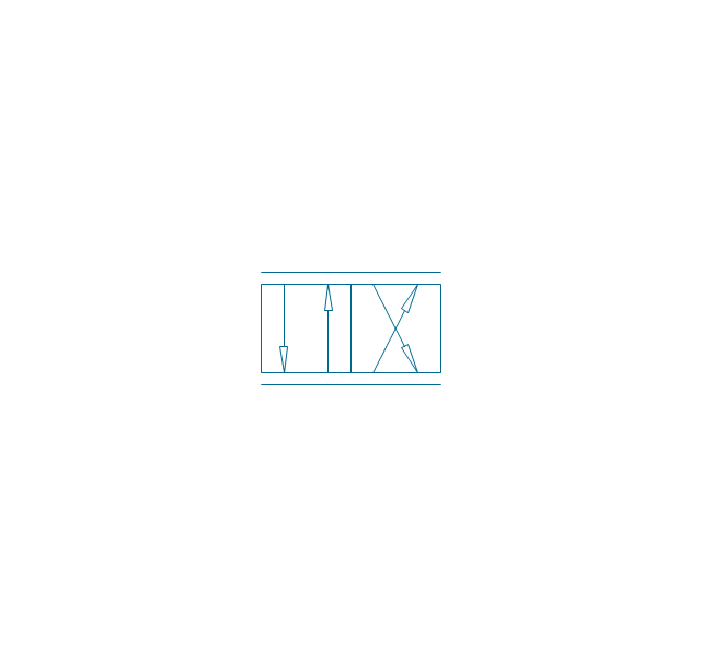
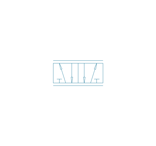
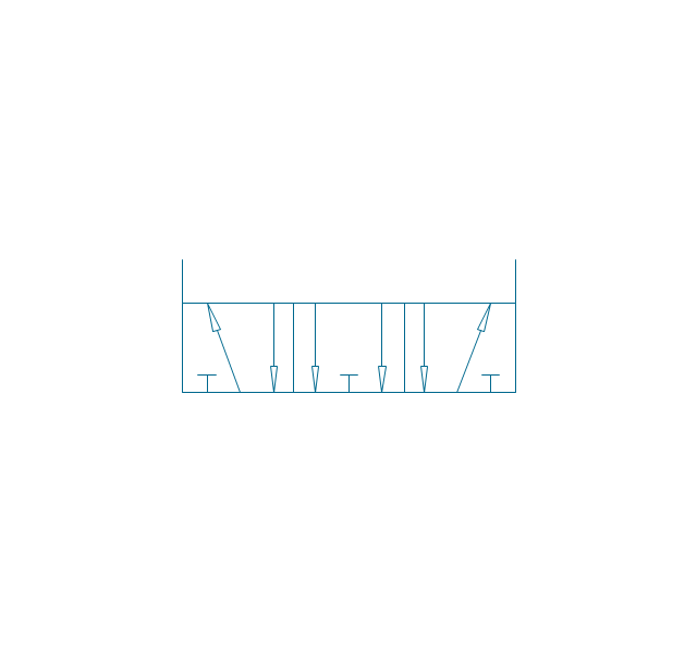
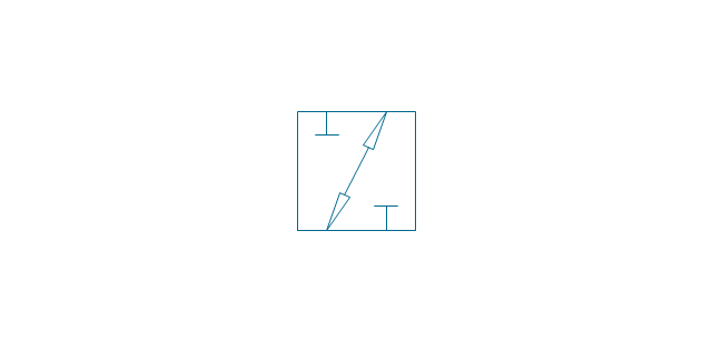
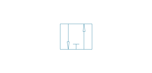
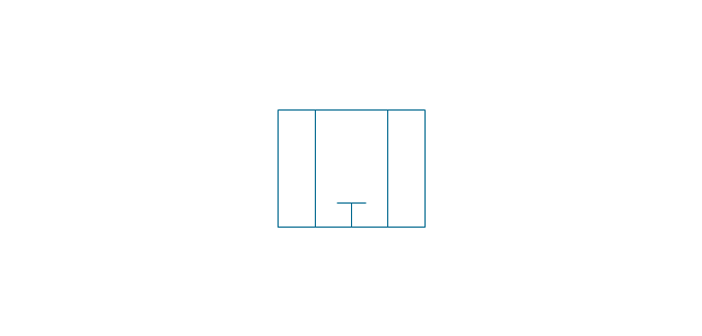
"Directional control valves route the fluid to the desired actuator. They usually consist of a spool inside a cast iron or steel housing. The spool slides to different positions in the housing, and intersecting grooves and channels route the fluid based on the spool's position. The spool has a central (neutral) position maintained with springs; in this position the supply fluid is blocked, or returned to tank. Sliding the spool to one side routes the hydraulic fluid to an actuator and provides a return path from the actuator to tank. When the spool is moved to the opposite direction the supply and return paths are switched. When the spool is allowed to return to neutral (center) position the actuator fluid paths are blocked, locking it in position. Directional control valves are usually designed to be stackable, with one valve for each hydraulic cylinder, and one fluid input supplying all the valves in the stack. Tolerances are very tight in order to handle the high pressure and avoid leaking, spools typically have a clearance with the housing of less than a thousandth of an inch (25 µm). The valve block will be mounted to the machine's frame with a three point pattern to avoid distorting the valve block and jamming the valve's sensitive components. The spool position may be actuated by mechanical levers, hydraulic pilot pressure, or solenoids which push the spool left or right. A seal allows part of the spool to protrude outside the housing, where it is accessible to the actuator. The main valve block is usually a stack of off the shelf directional control valves chosen by flow capacity and performance. Some valves are designed to be proportional (flow rate proportional to valve position), while others may be simply on-off. The control valve is one of the most expensive and sensitive parts of a hydraulic circuit." [Hydraulic machinery. Wikipedia]
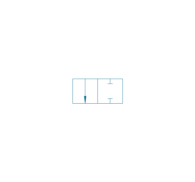
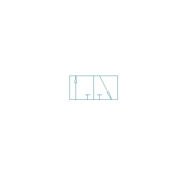
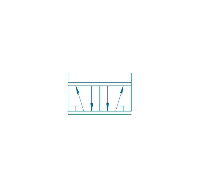
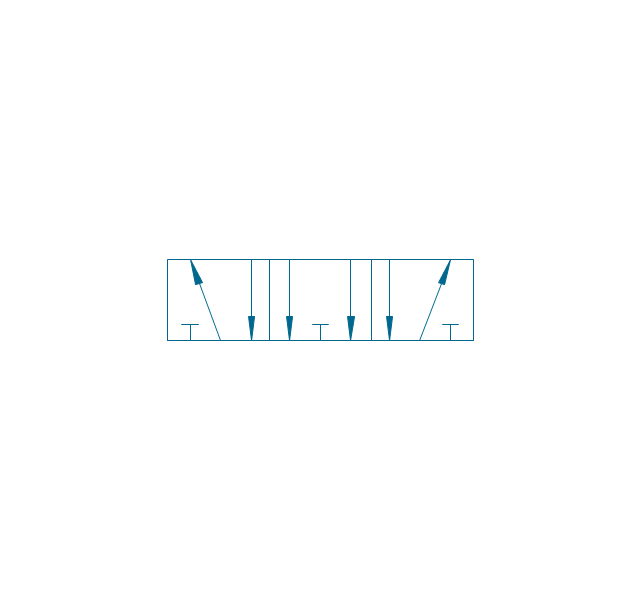
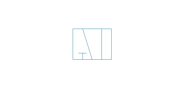
The Windows template "Hydraulic 4-ported 3-position valve" for the ConceptDraw PRO diagramming and vector drawing software is included in the Mechanical Engineering solution from the Engineering area of ConceptDraw Solution Park.
www.conceptdraw.com/ solution-park/ engineering-mechanical
The Windows template "Hydraulic 4-ported 3-position valve" for the ConceptDraw PRO diagramming and vector drawing software is included in the Mechanical Engineering solution from the Engineering area of ConceptDraw Solution Park.
www.conceptdraw.com/ solution-park/ engineering-mechanical
Hydraulic directional control valve

The vector stencils library "Valves" contains 91 symbols of piping and plumbing valves.
"A valve is a device that regulates, directs or controls the flow of a fluid (gases, liquids, fluidized solids, or slurries) by opening, closing, or partially obstructing various passageways. Valves are technically valves fittings, but are usually discussed as a separate category. In an open valve, fluid flows in a direction from higher pressure to lower pressure.
The simplest, and very ancient, valve is simply a freely hinged flap which drops to obstruct fluid (gas or liquid) flow in one direction, but is pushed open by flow in the opposite direction. This is called a check valve, as it prevents or "checks" the flow in one direction.
People in developed nations use valves in their daily lives, including plumbing valves, such as taps for tap water, gas control valves on cookers, small valves fitted to washing machines and dishwashers, safety devices fitted to hot water systems..." [Valve. Wikipedia]
Use the design elements library "Valves" to draw building plans, schematic diagrams, blueprints, or technical drawings of industrial piping systems; process, vacuum, and fluids piping; hydraulics piping; air and gas piping; materials distribution; and liquid transfer systems using the ConceptDraw PRO diagramming and vector drawing software.
The shapes library "Valves" is included in the Plumbing and Piping Plans solution from the Building Plans area of ConceptDraw Solution Park.
Valve symbols

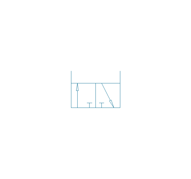
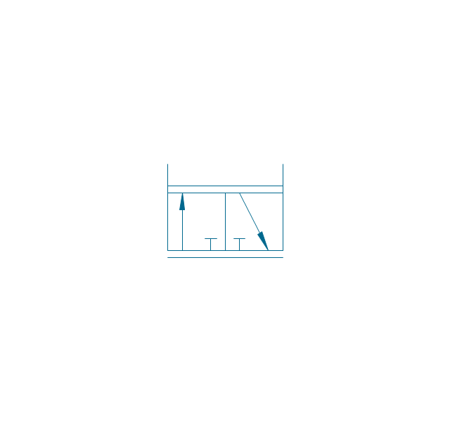
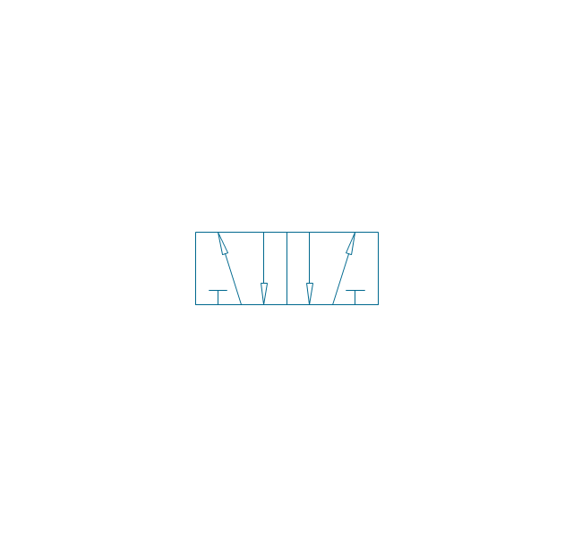
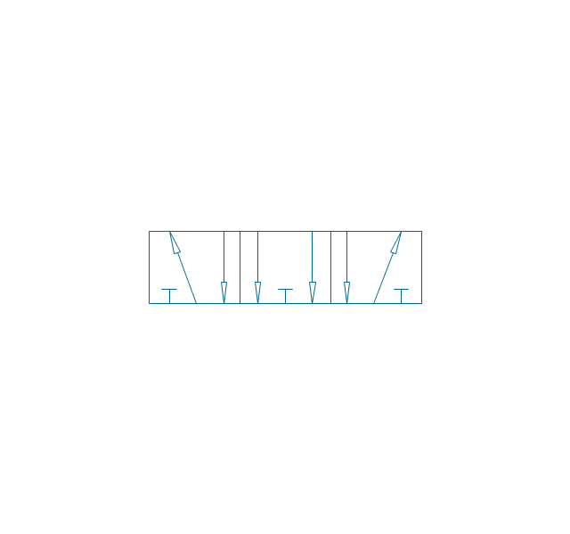
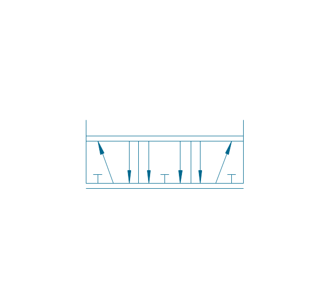
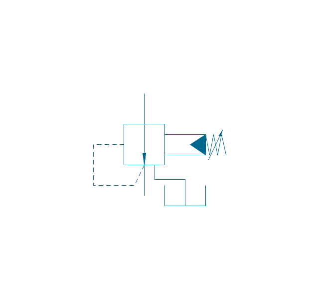
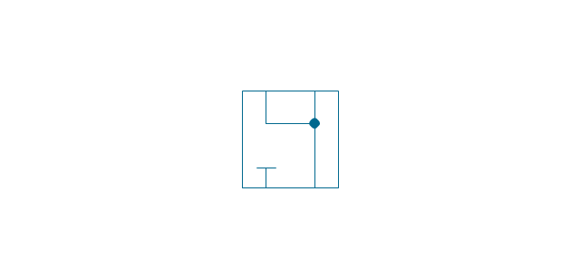
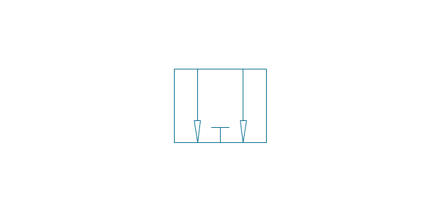
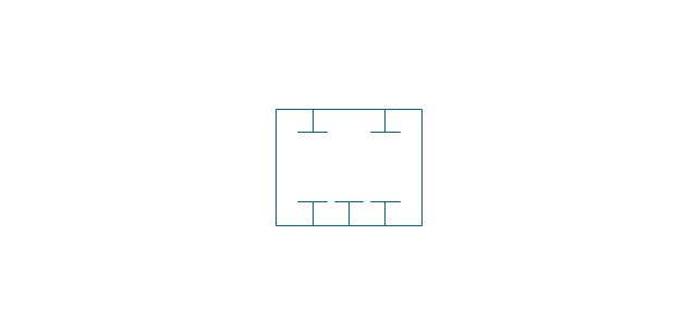
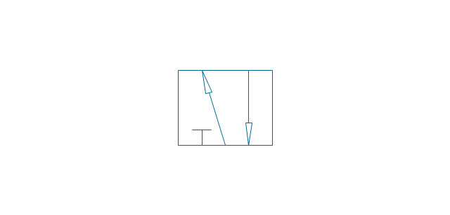
"An air-operated valve is a type of power operated valve that uses air pressure against a piston or diaphragm to produce linear or circular movement to operate a valve. Types are 2-way, 3-way and 4-way. The 2 way air-operated valves can be either normally closed or normally opened." [Air-operated valve. Wikipedia]
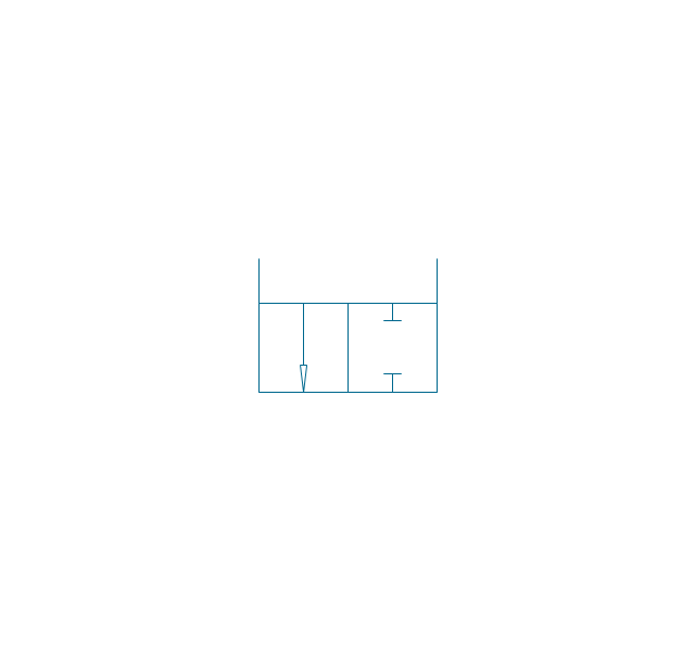
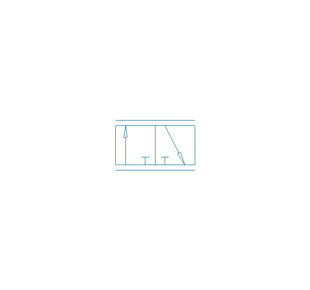
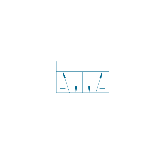
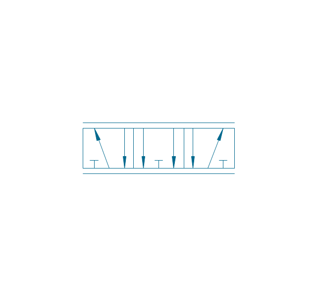
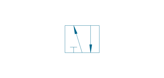
The Windows template "Pneumatic 4-ported 3-position valve" for the ConceptDraw PRO diagramming and vector drawing software is included in the Mechanical Engineering solution from the Engineering area of ConceptDraw Solution Park.
www.conceptdraw.com/ solution-park/ engineering-mechanical
The Windows template "Pneumatic 4-ported 3-position valve" for the ConceptDraw PRO diagramming and vector drawing software is included in the Mechanical Engineering solution from the Engineering area of ConceptDraw Solution Park.
www.conceptdraw.com/ solution-park/ engineering-mechanical
Pneumatic directional control valve
This example engineering drawing showing the hydraulic directional control valve usage with floating motor and pressure compensated pump is redesigned using the ConceptDraw PRO diagramming and vector drawing software from the Wikimedia Commons file: DCV 17.jpg.
[commons.wikimedia.org/ wiki/ File:DCV_ 17.jpg]
This file is licensed under the Creative Commons Attribution-Share Alike 3.0 Unported license.
[creativecommons.org/ licenses/ by-sa/ 3.0/ deed.en]
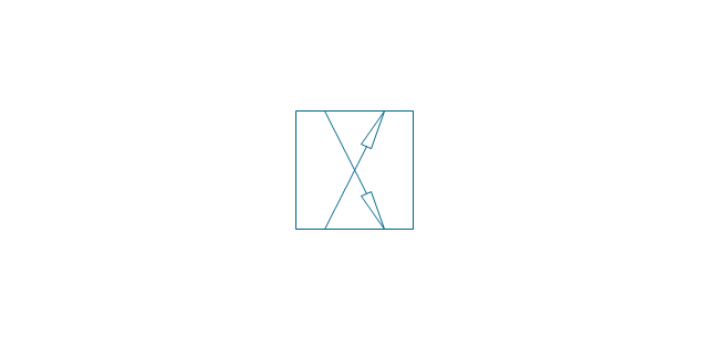
"Directional control valves are one of the most fundamental parts in hydraulic machinery as well and pneumatic machinery. They allow fluid flow into different paths from one or more sources. They usually consist of a spool inside a cylinder which is mechanically or electrically controlled. The movement of the spool restricts or permits the flow, thus it controls the fluid flow. ...
The spool (sliding type) consists of lands and grooves.The lands block oil flow through the valve body. The grooves allow oil or gas to flow around the spool and through the valve body. There are two fundamental positions of directional control valve namely normal position where valve returns on removal of actuating force and other is working position which is position of a valve when actuating force is applied. There is another class of valves with 3 or more position that can be spring centered with 2 working position and a normal position. ...
Directional control valves can be classified according to:
(1) number of ports;
(2) number of positions;
(3) actuating methods;
(4) type of spool." [Directional control valve. Wikipedia]
The fluid power equipment drawing example "Directional control valve" is included in the Mechanical Engineering solution from the Engineering area of ConceptDraw Solution Park.
[commons.wikimedia.org/ wiki/ File:DCV_ 17.jpg]
This file is licensed under the Creative Commons Attribution-Share Alike 3.0 Unported license.
[creativecommons.org/ licenses/ by-sa/ 3.0/ deed.en]
"Directional control valves are one of the most fundamental parts in hydraulic machinery as well and pneumatic machinery. They allow fluid flow into different paths from one or more sources. They usually consist of a spool inside a cylinder which is mechanically or electrically controlled. The movement of the spool restricts or permits the flow, thus it controls the fluid flow. ...
The spool (sliding type) consists of lands and grooves.The lands block oil flow through the valve body. The grooves allow oil or gas to flow around the spool and through the valve body. There are two fundamental positions of directional control valve namely normal position where valve returns on removal of actuating force and other is working position which is position of a valve when actuating force is applied. There is another class of valves with 3 or more position that can be spring centered with 2 working position and a normal position. ...
Directional control valves can be classified according to:
(1) number of ports;
(2) number of positions;
(3) actuating methods;
(4) type of spool." [Directional control valve. Wikipedia]
The fluid power equipment drawing example "Directional control valve" is included in the Mechanical Engineering solution from the Engineering area of ConceptDraw Solution Park.
Hydraulic equipment schematic

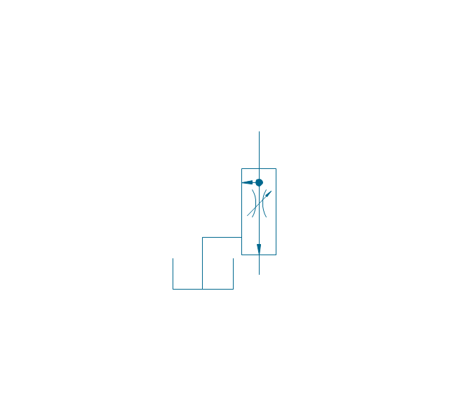
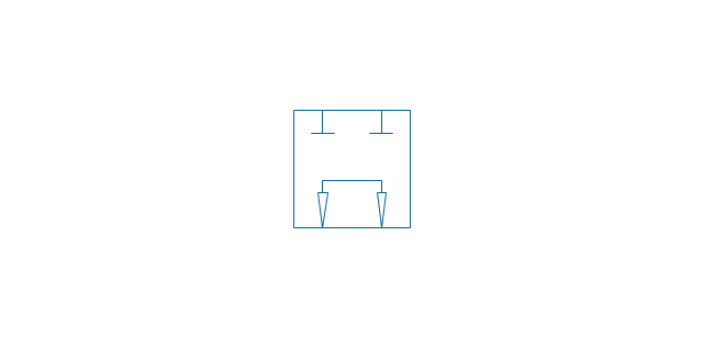
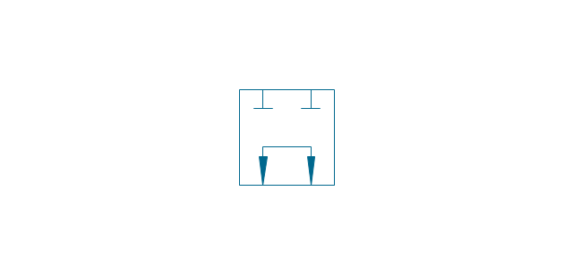
Retract resistor check valve application: pneumatic cylinder, piston driven by Compressed air through 2 Retract resistor check valves.
"A check valve, clack valve, non-return valve or one-way valve is a valve that normally allows fluid (liquid or gas) to flow through it in only one direction.
Check valves are two-port valves, meaning they have two openings in the body, one for fluid to enter and the other for fluid to leave. There are various types of check valves used in a wide variety of applications. Check valves are often part of common household items. Although they are available in a wide range of sizes and costs, check valves generally are very small, simple, or inexpensive. Check valves work automatically and most are not controlled by a person or any external control; accordingly, most do not have any valve handle or stem. The bodies (external shells) of most check valves are made of plastic or metal.
An important concept in check valves is the cracking pressure which is the minimum upstream pressure at which the valve will operate. Typically the check valve is designed for and can therefore be specified for a specific cracking pressure.
Heart valves are essentially inlet and outlet check valves for the heart ventricles, since the ventricles act as pumps." [Check valve. Wikipedia]
This hydraulic schematic example was redrawn using ConceptDraw PRO diagramming and vector drawing software from the Wikimedia Commons file: Retract resistor check valve application.png.
[commons.wikimedia.org/ wiki/ File:Retract_ resistor_ check_ valve_ application.png]
The hydraulic engineering drawing example "Retract resistor check valve application" was created using the ConceptDraw PRO diagramming and vector drawing software extended with the Mechanical Engineering solution from the Engineering area of ConceptDraw Solution Park.
Hydraulic schematic

Piping and Instrumentation Diagram Software

The vector stencils library "Valves" contains 91 symbols of valves. Use it for drawing plumbing and piping plans, schematic diagrams and blueprints of industrial piping systems; process, vacuum, and fluids piping; hydraulics piping; air and gas piping; materials distribution; and liquid transfer systems in the ConceptDraw PRO diagramming and vector drawing software extended with the Plumbing and Piping Plans solution from the Building Plans area of ConceptDraw Solution Park.
In-line valve

3-way valve

4-way valve

Screw-down valve

Lock-shield valve

Reel valve

Relief valve

Relief valve 2

Relief valve 3

Relief valve 4

Angle valve

Angle valve 2

Angle valve 3

Angle valve 4

Check valve

Check valve 2

Screwdown valve

Float operated valve

Float operated valve 2

Flanged valve

Flanged valve 2

Butterfly valve

Butterfly valve 2

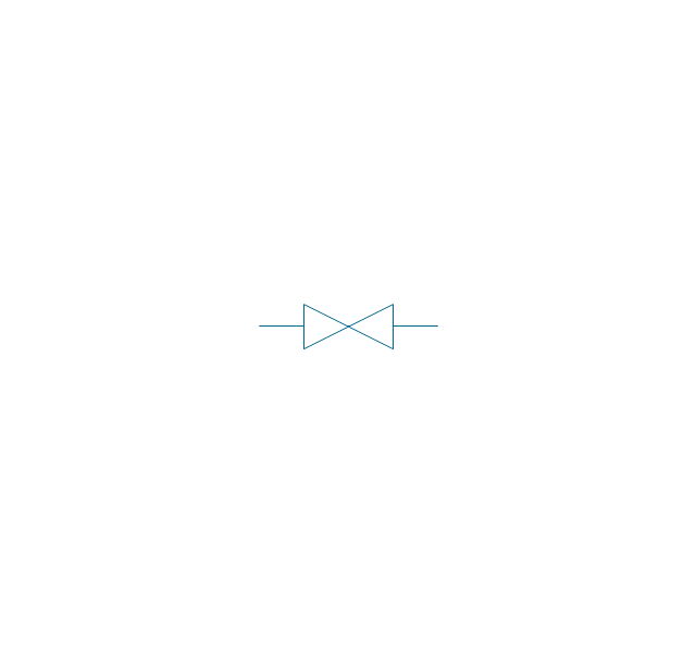
Globe valve

Globe valve 2

Globe valve 3

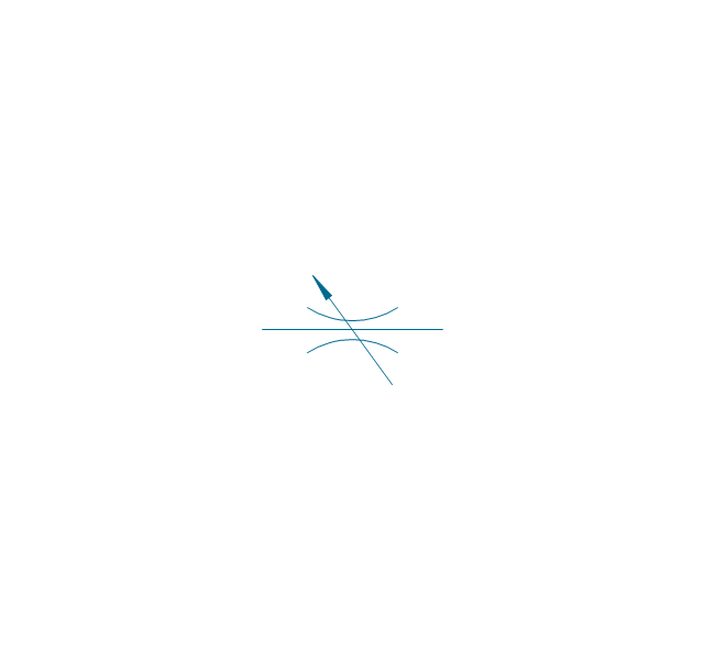
Needle valve

Needle valve 2

Needle valve 3

Needle valve 4

Diaphragm valve

Diaphragm valve 2

Diaphragm valve 3

Wedge gate valve

Parallel side valve

Gate valve

Ball valve

Ball valve 2

Ball valve 3

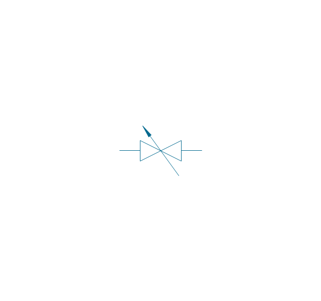
Powered control valve

Powered control valve 2

Powered control valve 3

Relief angle valve, pressure

Relief angle valve, vacuum

Reducing valve

Reducing valve 2

Plug valve

Plug valve 2

Plug valve, straight through

3-way plug valve

Plug valve, T-port

Plug valve, L-port

3-way plug valve

3-way plug valve 2

3-way plug valve 3

3-way plug valve, T-port

3-way plug valve, L-port

Mixing valve

Characterized port valve

Manual isolation

Power signal

Statically loaded

Spring loaded

Spring loaded 2

Remote control

Diaphragm

Diaphragm, positioner

Chain operated

Gear operated

Solenoid

Weight loaded

Weight loaded 2

Weight loaded 3

Float operated

Float operated 2

Dash-pot

Dash-pot 2

Piston

Quick opening

Quick opening 2

Quick closing

Quick closing 2

Connecting unit

Connecting unit 2

Connecting unit 3

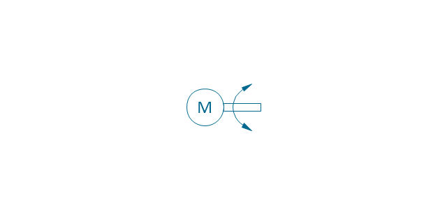
Motor element

Motor element, opens on failure

Motor element, closes on failure

Motor element, retains position on fail

Motor element, safe direction

Regulating

Interior Design. Piping Plan — Design Elements

Mechanical Drawing Software

HelpDesk
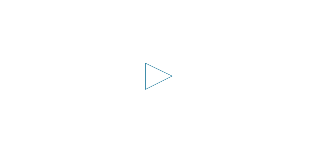
How to Draw a Vacuum Tube Circuit

The vector stencils library "Valves and fittings" contains 104 symbols of valve components.
Use these icons for drawing industrial piping systems; process, vacuum, and fluids piping; hydraulics piping; air and gas piping; materials distribution; and liquid transfer systems.
"A valve is a device that regulates, directs or controls the flow of a fluid (gases, liquids, fluidized solids, or slurries) by opening, closing, or partially obstructing various passageways. Valves are technically valves fittings, but are usually discussed as a separate category. In an open valve, fluid flows in a direction from higher pressure to lower pressure.
The simplest, and very ancient, valve is simply a freely hinged flap which drops to obstruct fluid (gas or liquid) flow in one direction, but is pushed open by flow in the opposite direction. This is called a check valve, as it prevents or "checks" the flow in one direction. ...
Valves are found in virtually every industrial process, including water & sewage processing, mining, power generation, processing of oil, gas & petroleum, food manufacturing, chemical & plastic manufacturing and many other fields. ...
Valves may be operated manually, either by a handle, lever, pedal or wheel. Valves may also be automatic, driven by changes in pressure, temperature, or flow. These changes may act upon a diaphragm or a piston which in turn activates the valve, examples of this type of valve found commonly are safety valves fitted to hot water systems or boilers.
More complex control systems using valves requiring automatic control based on an external input (i.e., regulating flow through a pipe to a changing set point) require an actuator. An actuator will stroke the valve depending on its input and set-up, allowing the valve to be positioned accurately, and allowing control over a variety of requirements." [Valve. Wikipedia]
The example "Design elements - Valves and fittings" was created using the ConceptDraw PRO diagramming and vector drawing software extended with the Chemical and Process Engineering solution from the Engineering area of ConceptDraw Solution Park.
Valves and fittings symbols

The vector stencils library "Valve assembly" contains 141 symbols of pressure and flow regulators, flow direction indicators, controls, and symbols to design flow paths of control valves in fluid power systems.
Use these valve assembly shapes to design the engineering drawings of hydraulic and pneumatic valve assemblies
in the ConceptDraw PRO diagramming and vector drawing software extended with the Mechanical Engineering solution from the Engineering area of ConceptDraw Solution Park.
www.conceptdraw.com/ solution-park/ engineering-mechanical
2 position 2,3,4 port (fin. pos.)
-valve-assembly---vector-stencils-library.png--diagram-flowchart-example.png)
2 position 2,3,4 port (infin. pos.)
-valve-assembly---vector-stencils-library.png--diagram-flowchart-example.png)
2 position 2,3,4 port (ext., fin.pos.)
-valve-assembly---vector-stencils-library.png--diagram-flowchart-example.png)
2 position 2,3,4 port (ext., infin. pos.)
-valve-assembly---vector-stencils-library.png--diagram-flowchart-example.png)
2 position 5 port (fin. pos.)
-valve-assembly---vector-stencils-library.png--diagram-flowchart-example.png)
2 position 5 port (infin. pos.)
-valve-assembly---vector-stencils-library.png--diagram-flowchart-example.png)
2 position 5 port (ext., fin.pos.)
-valve-assembly---vector-stencils-library.png--diagram-flowchart-example.png)
2 position 5 port (ext., infin. pos.)
-valve-assembly---vector-stencils-library.png--diagram-flowchart-example.png)
3 position 2,3,4 port (fin. pos.)
-valve-assembly---vector-stencils-library.png--diagram-flowchart-example.png)
3 position 2,3,4 port (infin. pos.)
-valve-assembly---vector-stencils-library.png--diagram-flowchart-example.png)
3 position 2,3,4 port (ext., fin.pos.)
-valve-assembly---vector-stencils-library.png--diagram-flowchart-example.png)
3 position 2,3,4 port (ext., infin. pos.)
-valve-assembly---vector-stencils-library.png--diagram-flowchart-example.png)
3 position 5 port (fin. pos.)
-valve-assembly---vector-stencils-library.png--diagram-flowchart-example.png)
3 position 5 port (infin. pos.)
-valve-assembly---vector-stencils-library.png--diagram-flowchart-example.png)
3 position 5 port (ext., fin.pos.)
-valve-assembly---vector-stencils-library.png--diagram-flowchart-example.png)
3 position 5 port (ext., infin. pos.)
-valve-assembly---vector-stencils-library.png--diagram-flowchart-example.png)
4 position 2,3,4 port (fin. pos.)
-valve-assembly---vector-stencils-library.png--diagram-flowchart-example.png)
4 position 2,3,4 port (infin. pos.)
-valve-assembly---vector-stencils-library.png--diagram-flowchart-example.png)
4 position 2,3,4 port (ext., fin.pos.)
-valve-assembly---vector-stencils-library.png--diagram-flowchart-example.png)
4 position 2,3,4 port (ext., infin. pos.)
-valve-assembly---vector-stencils-library.png--diagram-flowchart-example.png)
4 position 5 port (fin. pos.)
-valve-assembly---vector-stencils-library.png--diagram-flowchart-example.png)
4 position 5 port (infin. pos.)
-valve-assembly---vector-stencils-library.png--diagram-flowchart-example.png)
4 position 5 port (ext., fin.pos.)
-valve-assembly---vector-stencils-library.png--diagram-flowchart-example.png)
4 position 5 port (ext., infin. pos.)
-valve-assembly---vector-stencils-library.png--diagram-flowchart-example.png)
Box 5 port

Box 2,3,4 port

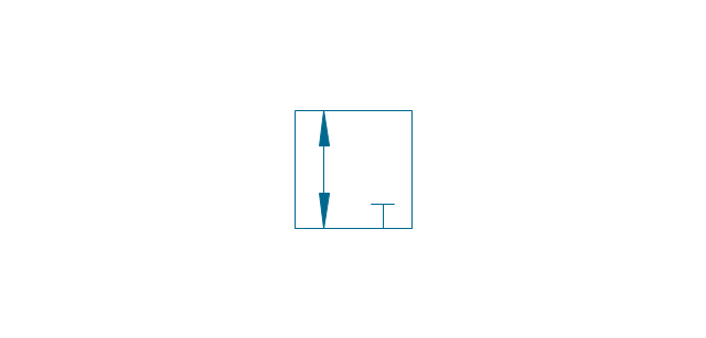
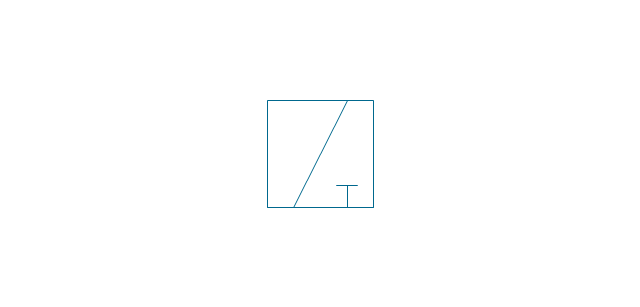
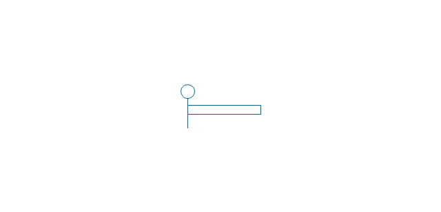
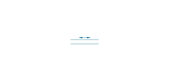
2-port, pneum., 1 arrow
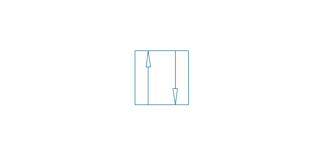
2-port, pneum., 2 arrows

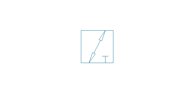
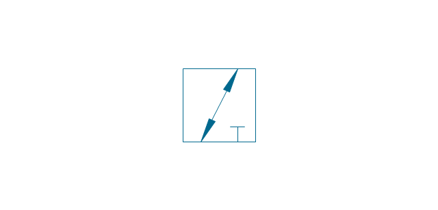
2-port, hydr., 1 arrow
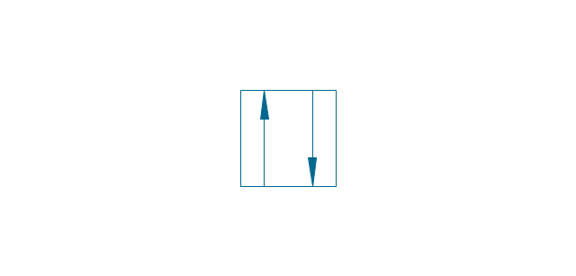
2-port, hydr., 2 arrows

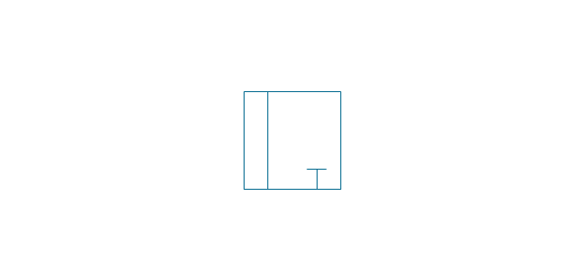
2-port

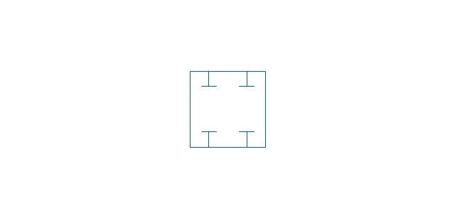
2-port closed

3-port, pneum., 1 arrow
3-port, pneum., 2 arrows
3-port, hydr., 1 arrow
3-port, hydr., 2 arrows
3-port
3-port crossover, pneum., 1 arrow
3-port crossover, pneum., 2 arrows
3-port crossover, hydr., 1 arrow
3-port crossover, hydr., 2 arrows
3-port crossover
4-port, pneum.
4-port, hydr.
4-port closed
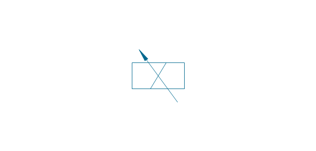
4-port crossed, pneum.
4-port crossed, hydr.

4-port tandem, pneum., 1 arrow
4-port tandem, pneum., 2 arrows
4-port tandem, hydr., 1 arrow
4-port tandem, hydr., 2 arrows
4-port tandem
4-port open
4-port semi-connected
4-port crossover, pneum., 1 arrow
4-port crossover, pneum., 2 arrows
4-port crossover, hydr., 1 arrow
4-port crossover, hydr., 2 arrows
4-port crossover
5-port, pneum., arrows same
5-port, pneum., arrows opposite
5-port, hydr., arrows same
5-port, hydr., arrows opposite
5-port
5-port closed
5-port crossover, pneum., arrows same
5-port crossover, pneum., arrows opposite
5-port crossover, hydr., arrows same
5-port crossover, hydr., arrows opposite
5-port crossover
Spring

Spring, var.
Plunger

Plunger, var.
Roller

Roller (arrow)
-valve-assembly---vector-stencils-library.png--diagram-flowchart-example.png)
One-way trip
One-way trip (arrow)
-valve-assembly---vector-stencils-library.png--diagram-flowchart-example.png)
Manual override

Pull button

Push button

Pull/push button
Lever
Pedal

Treadle

Electric rotor
Electric control, proportional, 1 winding
Electric control, proportional, 2 windings

Electric control, non-proportional, 1 winding

Electric control, non-proportional, 2 windings

Pilot-operated, pneum., 1 arrow, points left

Pilot-operated, pneum., 1 arrow, points right

Pilot-operated, pneum., 2 arrows, points left

Pilot-operated, pneum., 2 arrows, points right

Pilot-operated, pneum.

Pilot-operated, hydr., 1 arrow, points left

Pilot-operated, hydr., 1 arrow, points right

Pilot-operated, hydr., 2 arrows, points left

Pilot-operated, hydr., 2 arrows, points right

Pilot-operated, hydr.

Detent

Junction dot

T-junction, con.
T-junction, discon.
4-way junction, con.
4-way junction, discon.

Crossing
Flexible line
Air bleed, continuous

Air bleed, temporary

Fluid energy

Fluid energy, hydr.

Fluid energy, pneum.

Air exhaust port

Fluid flow, pneum.
Fluid flow, hydr.
Rotary connection (1)
-valve-assembly---vector-stencils-library.png--diagram-flowchart-example.png)
Rotary connection (3)
-valve-assembly---vector-stencils-library.png--diagram-flowchart-example.png)
Variable arrow
Curved arrow, top

Curved arrow, bottom

Curved arrow, both ends

Flow path

Flow path, pneum., 1 arrow
Flow path, hydr., 1 arrow
Flow path, pneum., 2 arrows

Flow path, hydr., 2 arrows

Shaft, top arrow
Shaft, bottom arrow
Shaft, both arrows

Shaft

Rod, right arrow
Rod, left arrow
Rod, both arrows
Over - center

Latch
Closed path

Electric

Restriction

Closed path (double)
-valve-assembly---vector-stencils-library.png--diagram-flowchart-example.png)
Temperature

Building Drawing Software for Designing Plumbing


A simple hydraulic schematic showing apparatus for testing the strength of a hydraulic hose splice.
Water enters through normally closed solenoid valve (1) and passes through intake flow meter (2) to high pressure pump (4). Intake water pressure is monitored by pressure gauge (3). The hose to be tested connects between pump (4) and normally open solenoid activated drain valve (7). To test the hose, pump drive motor (5) is turned on, the solenoid of drain valve (7) is activated, closing the valve, and the pump is run to pressurize the hose. Test pressure is monitored by gauge (6). When the test is complete or the hose fails, the solenoid of drain valve (7) is deactivated, opening valve and discharging water, depressurizing the system. All components are operated electrically by a remote control circuit so that the operator may perform the test from a protected location, monitoring it with a camera and video monitor.
This hydraulic schematic example was redrawn using ConceptDraw PRO diagramming and vector drawing software from the Wikimedia Commons file: Hydraulic schematic.jpg.
[commons.wikimedia.org/ wiki/ File:Hydraulic_ schematic.jpg]
This file is licensed under the Creative Commons Attribution-Share Alike 3.0 Unported license.
[creativecommons.org/ licenses/ by-sa/ 3.0/ deed.en]
The hydraulic schematic example "Apparatus for testing the strength of a hydraulic hose splice" is included in the Mechanical Engineering solution from the Engineering area of ConceptDraw Solution Park.
Hydraulic system schematic

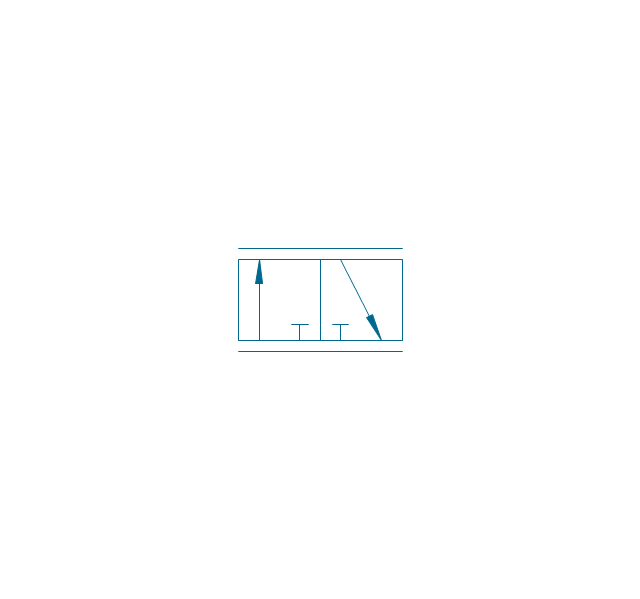
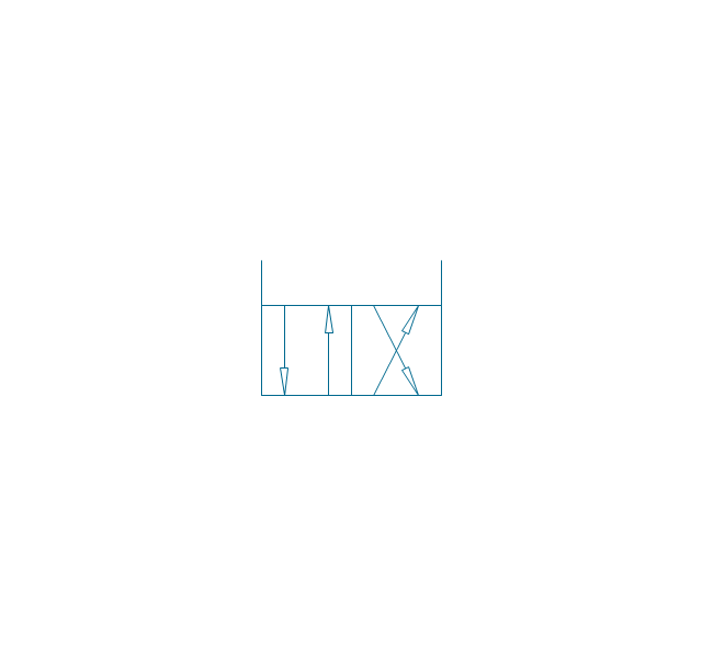
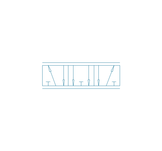
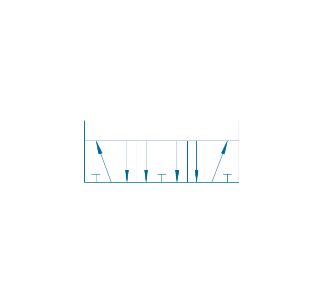
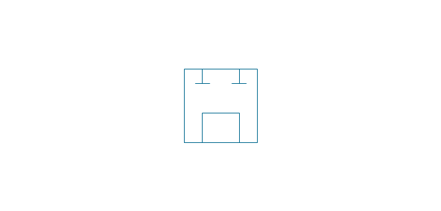
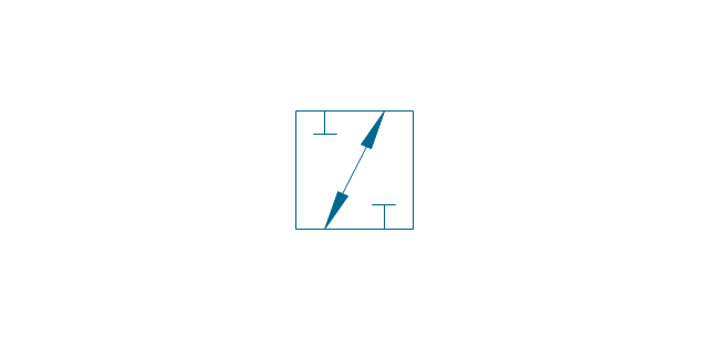
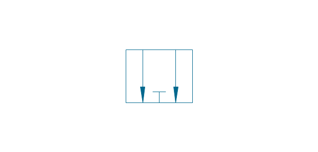
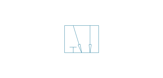
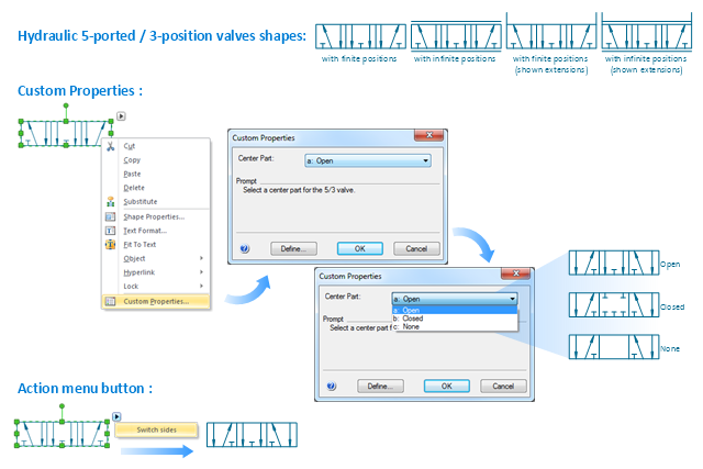
"Directional control valves are one of the most fundamental parts in hydraulic machinery as well and pneumatic machinery. They allow fluid flow into different paths from one or more sources. They usually consist of a spool inside a cylinder which is mechanically or electrically controlled. The movement of the spool restricts or permits the flow, thus it controls the fluid flow. ... Directional control valves can be classified according to: (1) number of ports; (2) number of positions; (3) actuating methods; (4) type of spool." [Directional control valve. Wikipedia]
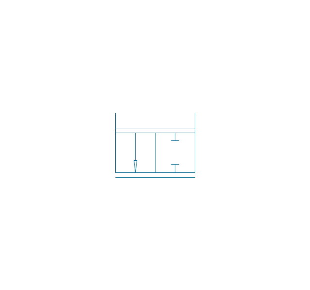
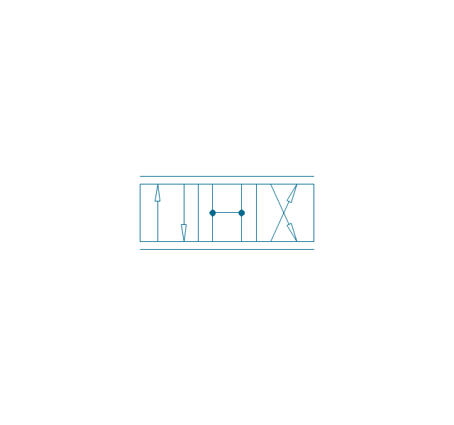
The Windows template "Hydraulic 5-ported 3-position valve" for the ConceptDraw PRO diagramming and vector drawing software is included in the Mechanical Engineering solution from the Engineering area of ConceptDraw Solution Park.
www.conceptdraw.com/ solution-park/ engineering-mechanical
The Windows template "Hydraulic 5-ported 3-position valve" for the ConceptDraw PRO diagramming and vector drawing software is included in the Mechanical Engineering solution from the Engineering area of ConceptDraw Solution Park.
www.conceptdraw.com/ solution-park/ engineering-mechanical
Hydraulic directional control valve
"A piping and instrumentation diagram/ drawing (P&ID) is a diagram in the process industry which shows the piping of the process flow together with the installed equipment and instrumentation. ...
P&IDs play a significant role in the maintenance and modification of the process that it describes. It is critical to demonstrate the physical sequence of equipment and systems, as well as how these systems connect. During the design stage, the diagram also provides the basis for the development of system control schemes, allowing for further safety and operational investigations, such as a Hazard Analysis and Operability Study...
For processing facilities, it is a pictorial representation of:
Key piping and instrument details,
Control and shutdown schemes,
Safety and regulatory requirements,
Basic start up and operational information." [Piping and instrumentation diagram. Wikipedia]
The piping and instrumentation diagram template for the ConceptDraw PRO diagramming and vector drawing software is included in the Chemical and Process Engineering solution from the Engineering area of ConceptDraw Solution Park.
Piping and instrumentation diagram / drawing (P&ID)
-piping-and-instrumentation-diagram-template.png--diagram-flowchart-example.png)
"Directional control valves are one of the most fundamental parts in hydraulic machinery as well and pneumatic machinery. They allow fluid flow into different paths from one or more sources. They usually consist of a spool inside a cylinder which is mechanically or electrically controlled. The movement of the spool restricts or permits the flow, thus it controls the fluid flow." [Directional control valve. Wikipedia]
This example engineering drawing showing the directional control valve usage with fixed volume pump and hydraulic cylinder is redesigned using the ConceptDraw PRO diagramming and vector drawing software from Wikimedia Commons file: DCV 19.jpg.
[commons.wikimedia.org/ wiki/ File:DCV_ 19.jpg]
This file is licensed under the Creative Commons Attribution-Share Alike 3.0 Unported license.
[creativecommons.org/ licenses/ by-sa/ 3.0/ deed.en]
The fluid power equipment drawing example "Directional control valve" is included in the Mechanical Engineering solution from the Engineering area of ConceptDraw Solution Park.
Hydraulic equipment schematic

- Process Flow Diagram Symbols | Schematic Symbols Of Valves
- Technical Drawing Software | Fluid power valves - Vector stencils ...
- Design elements - Valves | Design elements - Fluid power valves ...
- Technical Drawing Software | Hydraulic Valve Symbols Chart
- Mechanical Drawing Software | Retract resistor check valve ...
- Mechanical Engineering | Technical Drawing Software
- Mechanical Engineering | Technical Drawing Software | One Way ...
- Mechanical Drawing Software | Pneumatic 5-ported 3-position valve ...
- Mechanical Drawing Symbols | Design elements - Valve assembly ...
- Process Flow Chart | Technical Drawing Software | Mechanical ...