This vector stencils library contains 12 object schematic symbols.
Use it to design your IDEF3 diagrams with ConceptDraw PRO diagramming and vector drawing tools.
The vector stencils library "IDEF3 object schematic symbols" is included in the IDEF Business Process Diagrams solution from the Business Processes area of ConceptDraw Solution Park.
Use it to design your IDEF3 diagrams with ConceptDraw PRO diagramming and vector drawing tools.
The vector stencils library "IDEF3 object schematic symbols" is included in the IDEF Business Process Diagrams solution from the Business Processes area of ConceptDraw Solution Park.
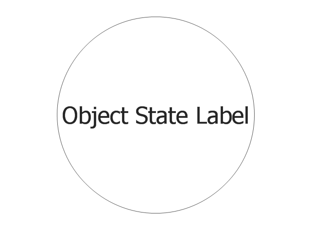
Object
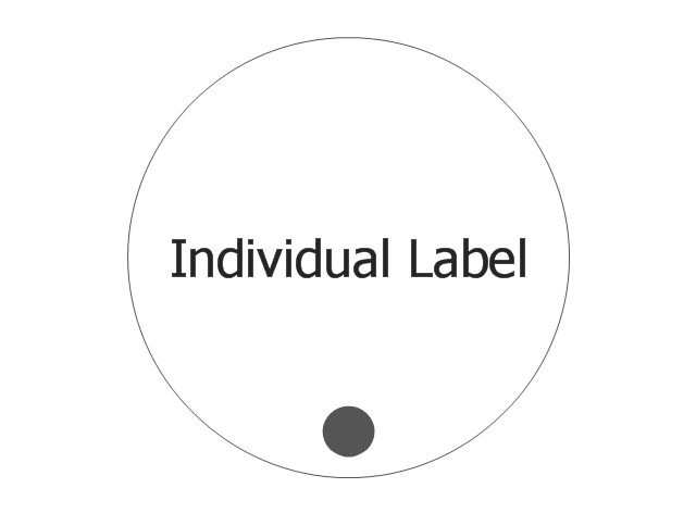
Individual
Weak Transition Link
Strong Transition Link
n-Place 1st-order Relation
2-Place 2nd-order Relation
AND Junction (object)
-vector-stencils-library---idef3-object-schematic-symbols.png--diagram-flowchart-example.png)
OR Junction (object)
-vector-stencils-library---idef3-object-schematic-symbols.png--diagram-flowchart-example.png)
XOR Junction (object)
-vector-stencils-library---idef3-object-schematic-symbols.png--diagram-flowchart-example.png)
Connecting arrow
Connecting line

Temporal Indeterminacy Marker

The vector stencils library "IDEF3 object schematic symbols" contains 12 shapes: objects, links, relations, junctions, connection arrow and line, temporal indeterminacy marker. Use it to design your IDEF3 object schematic diagrams.
"Object Schematics.
IDEF offers a series of building blocks to express detailed object-centered process information; that is, information about how objects of various kinds are transformed into other kinds of things through a process, or how objects of a given kind change states through a process.
- Objects : An object of a certain kind, like a chassis, will be represented simply by a circle containing an appropriate label.
- Object States : A certain kind of object being in a certain state will be represented by a circle with a label that captures the kind itself and a corresponding state, representing thereby the type, or class, of objects that are in that state.
- Object schematics : The construction of complex representations built from kind symbols and object state symbols.
- Transition Schematics : The first and most basic construct is the basic state transition schematic or simply, transition schematic." [IDEF3. Wikipedia]
The shapes example "Design elements - IDEF3 object schematic symbols" was created using the ConceptDraw PRO diagramming and vector drawing software extended with the solution "IDEF Business Process Diagrams" from the area "Business Processes" of ConceptDraw Solution Park.
IDEF3 object schematic symbols

Electrical Symbols — Terminals and Connectors

Electrical Symbols — Analog and Digital Logic

Electrical Symbols — Maintenance

Electrical Symbols — Resistors

Electrical Symbols — Lamps, Acoustics, Readouts

Electrical Symbols — Logic Gate Diagram

Electrical Symbols — Qualifying

Object-Oriented Design

Electrical Symbols — Electrical Circuits

How To use House Electrical Plan Software


Electrical Symbols — Transformers and Windings

Electrical Symbols — Thermo

Electrical Symbols — Rotating Equipment

- Design elements - IDEF3 object schematic symbols
- Vector stencils library - IDEF3 object schematic symbols | Electrical ...
- Design elements - IDEF3 process schematic symbols | Vector ...
- Vector stencils library - IDEF3 object schematic symbols | Vector ...
- Construction And Schematic Symbol
- Vector stencils library - IDEF3 object schematic symbols
- Electrical Symbols , Electrical Schematic Symbols | Process Flow ...
- Electrical Symbols , Electrical Diagram Symbols | Electrical Symbols ...
- Electrical Symbols — Switches and Relays | Basic Flowchart ...
- Electrical Symbols , Electrical Diagram Symbols | Electrical Symbols ...
- Electrical Symbols , Electrical Schematic Symbols | Electrical ...
- The Symbol For Circuit Breaker Used In Wiring Circuit Diagram
- Electrical Symbols , Electrical Diagram Symbols | How To use House ...
- Electrical Symbols , Electrical Diagram Symbols | Block Diagram ...
- Transition schematic - IDEF3 diagram example | Completed ...
- Process Flowchart | IDEF3 object state transition schematic | IDEF ...
- Electrical Symbols — Switches and Relays | Electrical Symbols ...
- Electrical Symbols — Thermo | Electrical Symbols — Resistors ...
- Electrical Symbols — Logic Gate Diagram | Electrical Symbols ...
- Electrical Symbols , Electrical Diagram Symbols | Electrical Drawing ...