
Network Drawing Software


Network Layout

Netflow architecture. Computer and Network Examples

"Logical topology, or signal topology, is the arrangement of devices on a computer network and how they communicate with one another. How devices are connected to the network through the actual cables that transmit data, or the physical structure of the network, is called the physical topology. Physical topology defines how the systems are physically connected. It represents the physical layout of the devices on the network. The logical topology defines how the systems communicate across the physical topologies.
Logical topologies are bound to network protocols and describe how data is moved across the network. ...
EXAMPLE : twisted pair Ethernet is a logical bus topology in a physical star topology layout. while IBM's token ring is a logical ring topology, it is physically set up in star topology." [Logical topology. Wikipedia]
This Cisco logical computer network diagram example was created using the ConceptDraw PRO diagramming and vector drawing software extended with the Cisco Network Diagrams solution from the Computer and Networks area of ConceptDraw Solution Park.
Logical network topology diagram

Design Element: Cisco for Network Diagrams

The vector stencils library "Logical network diagram" contains 16 symbols for drawing logical computer network diagrams.
"The logical topology ... is the way that the signals act on the network media, or the way that the data passes through the network from one device to the next without regard to the physical interconnection of the devices. A network's logical topology is not necessarily the same as its physical topology. ...
The logical classification of network topologies generally follows the same classifications as those in the physical classifications of network topologies but describes the path that the data takes between nodes being used as opposed to the actual physical connections between nodes. The logical topologies are generally determined by network protocols as opposed to being determined by the physical layout of cables, wires, and network devices or by the flow of the electrical signals, although in many cases the paths that the electrical signals take between nodes may closely match the logical flow of data, hence the convention of using the terms logical topology and signal topology interchangeably.
Logical topologies are often closely associated with Media Access Control methods and protocols. Logical topologies are able to be dynamically reconfigured by special types of equipment such as routers and switches." [Network topology. Wikipedia]
The symbols example "Logical network diagram - Vector stencils library" was created using the ConceptDraw PRO diagramming and vector drawing software extended with the Computer and Networks solution from the Computer and Networks area of ConceptDraw Solution Park.
www.conceptdraw.com/ solution-park/ computer-and-networks
Server

Disk

Printer

Domain

Network

File

Group

Root

Shared Admin

Directory

Tree

NDS Container

Unknown

Neightborhood

Service

Information

Network Hubs

The vector stencils library "Cisco WAN" contains 15 symbols of wide area network (WAN) devices and equipment for drawing Cisco WAN diagrams.
"A wide area network (WAN) is a network that covers a broad area (i.e., any telecommunications network that links across metropolitan, regional, or national boundaries) using leased telecommunication lines. Business and government entities utilize WANs to relay data among employees, clients, buyers, and suppliers from various geographical locations. ...
Related terms for other types of networks are personal area networks (PANs), local area networks (LANs), campus area networks (CANs), or metropolitan area networks (MANs) which are usually limited to a room, building, campus or specific metropolitan area (e.g., a city) respectively.
... it may be best to view WANs as computer networking technologies used to transmit data over long distances, and between different LANs, MANs and other localised computer networking architectures. ...
WANs are often built using leased lines. At each end of the leased line, a router connects the LAN on one side with a second router within the LAN on the other. Leased lines can be very expensive. Instead of using leased lines, WANs can also be built using less costly circuit switching or packet switching methods. Network protocols including TCP/ IP deliver transport and addressing functions. Protocols including Packet over SONET/ SDH, MPLS, ATM and Frame relay are often used by service providers to deliver the links that are used in WANs." [Wide area network. Wikipedia]
The symbols example "Cisco WAN - Vector stencils library" was created using the ConceptDraw PRO diagramming and vector drawing software extended with the Cisco Network Diagrams solution from the Computer and Networks area of ConceptDraw Solution Park.
www.conceptdraw.com/ solution-park/ computer-networks-cisco
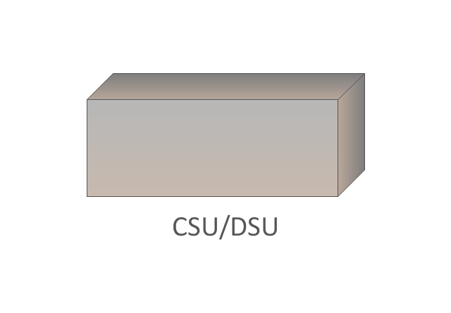
CSU/DSU
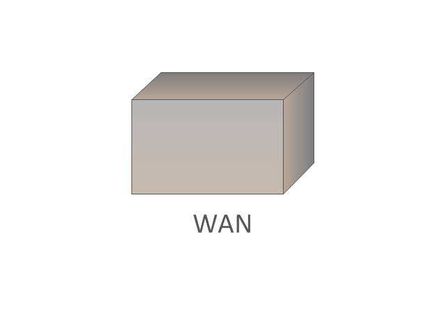
WAN
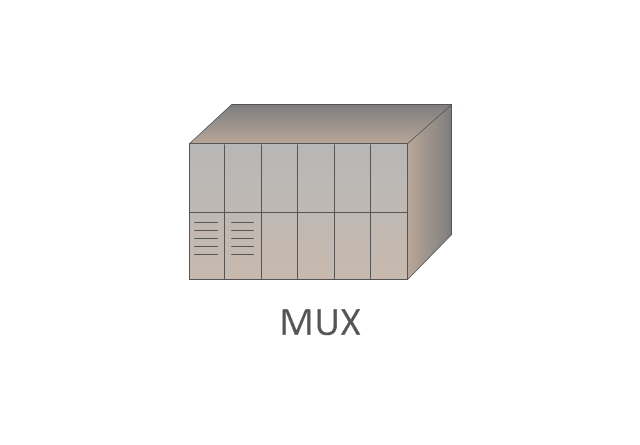
MUX
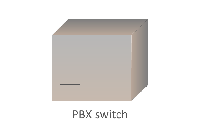
PBX switch
Hub
Hub, blue
NAT

Network cloud, dark
Network cloud, gold
Network cloud, white
Network cloud, standard color
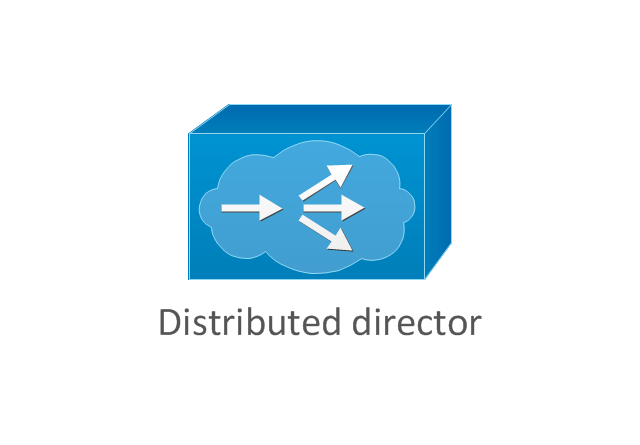
Distributed director
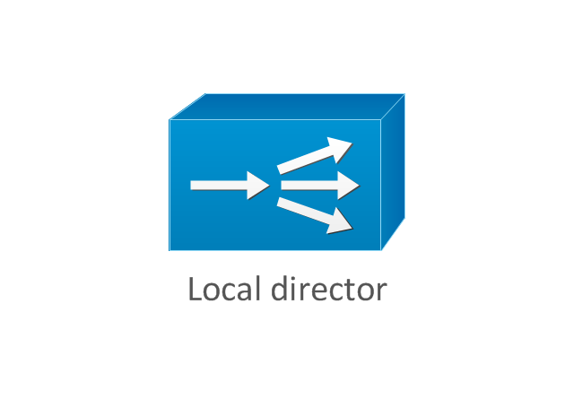
Local director
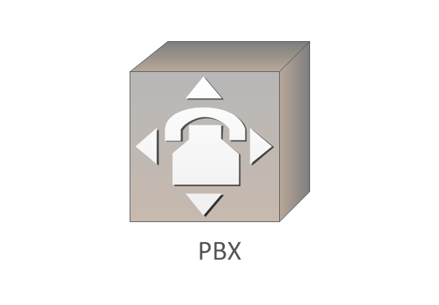
PBX
DPT
Vehicular Network

Multiprotocol Label Switching (MPLS). Computer and Network Examples
. <br>Computer and Network Examples *")
Hotel Network Topology Diagram. Hotel Guesthouse WiFi Network

ConceptDraw Arrows10 Technology

Network Topologies


Powerful Drawing Feature for Creating Professional Diagrams

Internet Group Management Protocol (IGMP). Computer and Network Examples
. <br>Computer and Network Examples *")
Pyramid Diagram

Network Security Devices

EIGRP. Computer and Network Examples

Network diagrams with ConceptDraw DIAGRAM

- Logical network topology diagram | Network Protocols | Logical ...
- Local area network (LAN). Computer and Network Examples ...
- Network Protocols | Computer Network Architecture. Computer and ...
- Network Protocols | Wireless Network WAN | Wireless Network ...
- Network Protocols | Basic Network Diagram | Computer and ...
- Network Protocols | UML state machine diagram - Template | IDEF4 ...
- Network Protocols | Telecommunication Network Diagrams | Wimax ...
- Mobile satellite TV network diagram | Network Protocols | Design ...
- Network Protocols | Building Plans Area | Draw The Block Diagram ...
- Home wireless network diagram | Wireless Networks | Network ...
- Multiprotocol Label Switching (MPLS). Computer and Network ...
- Design elements - Network layout floorplan | Network Protocols ...
- Network Hubs | Network Protocols | Schematic For Wifi Router
- Network Protocols | Telecommunication Network Diagrams ...
- Network Protocols | Base Station Symbol In Visio
- Network Protocols | Telecommunication Network Diagrams ...
- Network Printer | MS Visio Look a Like Diagrams | Network Protocols ...
- Wireless broadband network diagram | Network Protocols | Tranzeo ...
- Logical symbols - Vector stencils library | Network Protocols ...