Network Security Devices
Assurance of network security is one of the most important moments for safe and correct working of the computer systems and networks. The network security includes assurance of the limited access to sensitive information, the protection from unauthorized access, risks and potential security threats, and enhancement of network performance. It is necessary to protect the network at all of its entry points, the most important factors in network security are encryption, reliable passwords, the use of antivirus software and modern advanced network security devices.
There are few types of network security devices:
- active devices - firewalls, antivirus scanning devices, content filtering devices, which block the surplus traffic;
- passive devices, such as intrusion detection appliances, which identify and report on unwanted traffic;
- preventative devices - penetration testing devices and vulnerability assessment appliances, which scan the networks and identify potential security problems;
- Unified Threat Management (UTM) devices, such as firewalls, content filtering, web caching, which serve as all-in-one security devices.
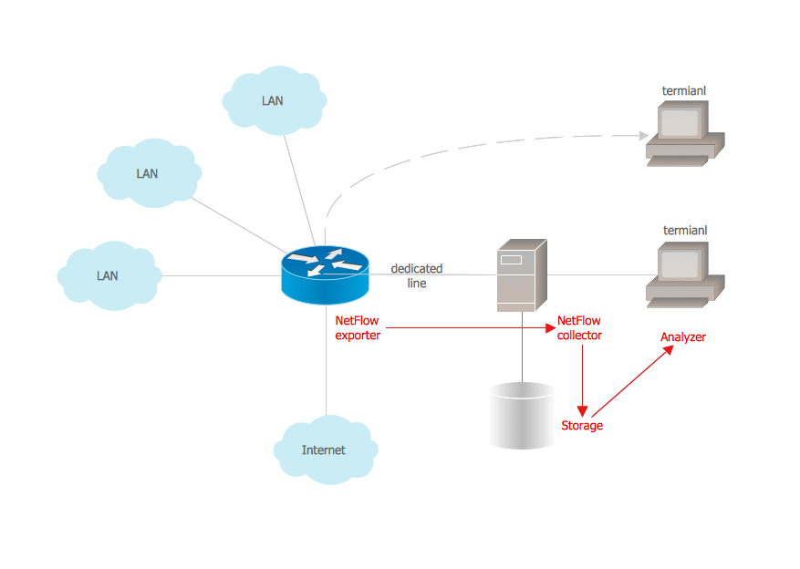
The most popular network security devices are firewalls - network security systems which establish a barrier between an internal network and the Internet, effectively manage and regulate the network traffic based on some protocols. Firewall can be software or hardware appliance, or include together hardware and software devices, most computers use software-based firewalls to secure their data from Internet threats, many routers also contain the firewall components.
Such network security devices as routers, crypto-capable routers, virtual private network gateways, secure modems and intrusion detection systems are also very popular. Intrusion detection systems are devices that monitor malicious activities in a network, log information about such activities and take active steps to stop them, and then report them.
How to describe the necessity of using network security devices and visually illustrate this information? Now, it's very easy thanks to the ConceptDraw DIAGRAM diagramming and vector drawing software extended with Network Security Diagrams Solution from the Computer and Networks Area of ConceptDraw Solution Park.

Example 1. Network Security Devices
The drawing tools of Network Security Diagrams Solution are very useful for network security design. This solution offers large collection of predesigned vector security clipart, icons, connectors and vector objects of network security devices developed by professional designers specially for ConceptDraw DIAGRAM users. All these 460 vector objects are grouped in 4 libraries:
- Cybersecurity Clipart
- Cybersecurity Round Icons
- Cybersecurity Shapes
- Cybersecurity Connectors

Example 2. Cybersecurity Clipart Library Design Elements
Each of these objects is ready-to-use. All that you need is simply double-click the icon at the library to add the chosen object in a moment to the middle of your document. Another way is to drag desired object from the library to the document page. Then you can arrange the objects, connect the objects in a desired way, add the text and make formatting changes.

Example 3. Network Security Diagram - Government Cloud Diagram
The samples you see on this page were created in ConceptDraw DIAGRAM using the tools of Network Security Diagrams Solution for ConceptDraw DIAGRAM software and demonstrate network security schemes with using the network security devices. An experienced user spent 10 minutes creating each of these samples.
Use the Network Security Diagrams Solution for ConceptDraw DIAGRAM to create your own Network Security Diagrams quick, easy and effective.
All source documents are vector graphic documents. They are available for reviewing, modifying, or converting to a variety of formats (PDF file, MS PowerPoint, MS Visio, and many other graphic formats) from the ConceptDraw STORE. The Network Security Diagrams Solution is available for all ConceptDraw DIAGRAM users.