 Telecommunication Network Diagrams
Telecommunication Network Diagrams solution extends ConceptDraw DIAGRAM software with samples, templates, and great collection of vector stencils to help the specialists in a field of networks and telecommunications, as well as other users to create Computer systems networking and Telecommunication network diagrams for various fields, to organize the work of call centers, to design the GPRS networks and GPS navigational systems, mobile, satellite and hybrid communication networks, to construct the mobile TV networks and wireless broadband networks.
Personal area (PAN) networks. Computer and Network Examples
 networks")

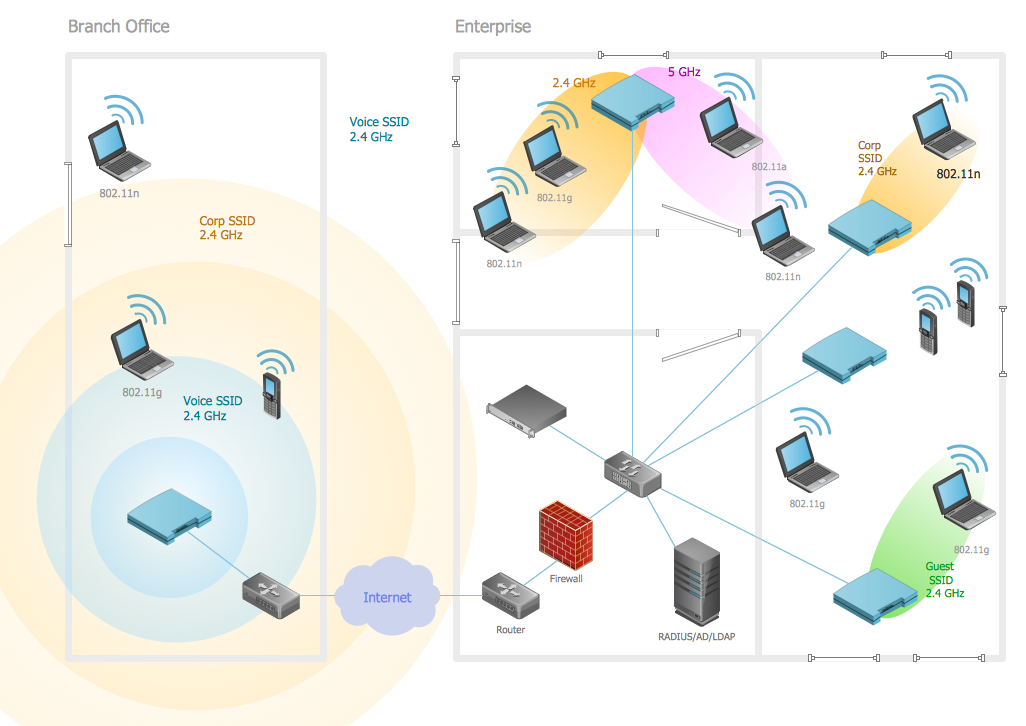
 Wireless Networks
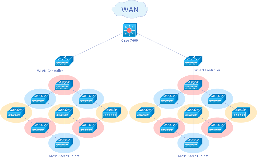
The Wireless Networks Solution extends ConceptDraw DIAGRAM software with professional diagramming tools, set of wireless network diagram templates and samples, comprehensive library of wireless communications and WLAN objects to help network engineers and designers efficiently design and create Wireless network diagrams that illustrate wireless networks of any speed and complexity, and help to identify all required equipment for construction and updating wireless networks, and calculating their costs.
3D Network Diagram Software

Wireless Networking
Wireless Network Drawing
UML Use Case Diagram Example. Social Networking Sites Project

Entity Relationship Diagram - ERD - Software for Design Crows Foot ER Diagrams
_Win_Mac.png)

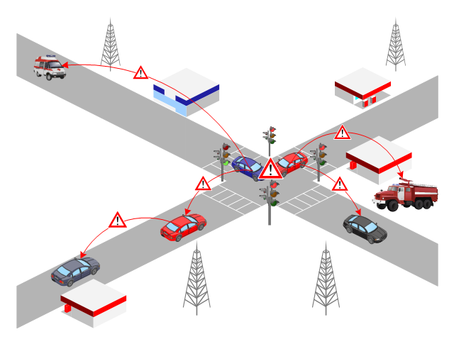
This VANET diagram example was drawn on the base of picture from the webpage "Security and Privacy in Location-based MANETs/ VANETs" from the Donald Bren School of Information and Computer Sciences, the University of California, Irvine. [ics.uci.edu/ ~keldefra/ manet.htm]
"A vehicular ad hoc network (VANET) uses cars as mobile nodes in a MANET to create a mobile network. A VANET turns every participating car into a wireless router or node, allowing cars approximately 100 to 300 metres of each other to connect and, in turn, create a network with a wide range. As cars fall out of the signal range and drop out of the network, other cars can join in, connecting vehicles to one another so that a mobile Internet is created. It is estimated that the first systems that will integrate this technology are police and fire vehicles to communicate with each other for safety purposes. Automotive companies like General Motors, Toyota, Nissan, DaimlerChrysler, BMW and Ford promote this term." [Vehicular ad hoc network. Wikipedia]
The VANET diagram example "Vehicular ad-hoc network" was created using the ConceptDraw PRO diagramming and vector drawing software extended with the Vehicular Networking solution from the Computer and Networks area of ConceptDraw Solution Park.
VANET diagram
 AWS Architecture Diagrams
AWS Architecture Diagrams with powerful drawing tools and numerous predesigned Amazon icons and AWS simple icons is the best for creation the AWS Architecture Diagrams, describing the use of Amazon Web Services or Amazon Cloud Services, their application for development and implementation the systems running on the AWS infrastructure. The multifarious samples give you the good understanding of AWS platform, its structure, services, resources and features, wide opportunities, advantages and benefits from their use; solution’s templates are essential and helpful when designing, description and implementing the AWS infrastructure-based systems. Use them in technical documentation, advertising and marketing materials, in specifications, presentation slides, whitepapers, datasheets, posters, etc.
Local area network (LAN). Computer and Network Examples
 diagram")
Cisco Products Additional. Cisco icons, shapes, stencils and symbols

 Interactive Voice Response Diagrams
Interactive Voice Response Diagrams solution extends ConceptDraw DIAGRAM software with samples, templates and libraries of ready-to-use vector stencils that help create Interactive Voice Response (IVR) diagrams illustrating in details a work of interactive voice response system, the IVR system’s logical and physical structure, Voice-over-Internet Protocol (VoIP) diagrams, and Action VoIP diagrams with representing voice actions on them, to visualize how the computers interact with callers through voice recognition and dual-tone multi-frequency signaling (DTMF) keypad inputs.
Network Security Devices

- Mobile cloud architecture diagram | Business Process Model and ...
- Mobile Network Architecture Diagram
- 3g Mobile Communication Model Diagram
- Telecommunication Network Diagrams | Telecommunication ...
- How to Create a Telecommunication Network Diagram in ...
- UML Use Case Diagram Example Social Networking Sites Project ...
- Telephone Network Model Diagram
- Telecommunication Network Diagrams | AWS Architecture Diagrams ...
- Wireless Networking Model Diagram
- Hybrid satellite and common carrier network diagram | Mobile ...
- Telecommunication Network Diagrams | Providing telecom services ...
- Local area network (LAN). Computer and Network Examples ...
- Mobile cloud architecture diagram | ER Diagram for Cloud ...
- AWS Architecture Diagrams | UML component diagram - Start server ...
- Example Of Network Model With Diagram
- Wide area network (WAN) topology. Computer and Network ...
- Wireless router network diagram | What Is a Wireless Network ...
- Cloud Computing diagram | Cloud applications | Mobile cloud ...
- Interactive Voice Response Diagrams | Mesh Network Topology ...
- Mobile Phone Networks