3D Network Diagram Software
How To Draw 3D Network Diagram
Visually communicate computer networks architecture, topology and design to simplify and accelerate understanding, analysis, and representation.
ConceptDraw has numerous examples of 3D network diagrams:
- Call Center Network Diagram
- Communication Medium Diagram
- Computer Network Diagram
- GPRS Network Scheme
- GPS Operation Diagram
- Hybrid Network Diagram
- Mobile Satellite Communication Network
- Mobile TV Network Diagram
- Terrestrial Mobile TV Network Diagram
- Web-based Network Diagram
- Wireless Broadband Network Diagram
- Wireless Router Network Diagram
Use more than 2 000 pre-designed 3D network elements for customizing your network diagrams. Computer & Networks solution allows you for design 3D LAN and WAN, schematic and wiring drawings.

Example 1. 3D Network Diagram symbols
Use ConceptDraw DIAGRAM software with tools of Computer & Networks solution for drawing 3D computer communication network architecture, topology, logic and wiring diagrams, LAN and WAN schematic drawings and maps.
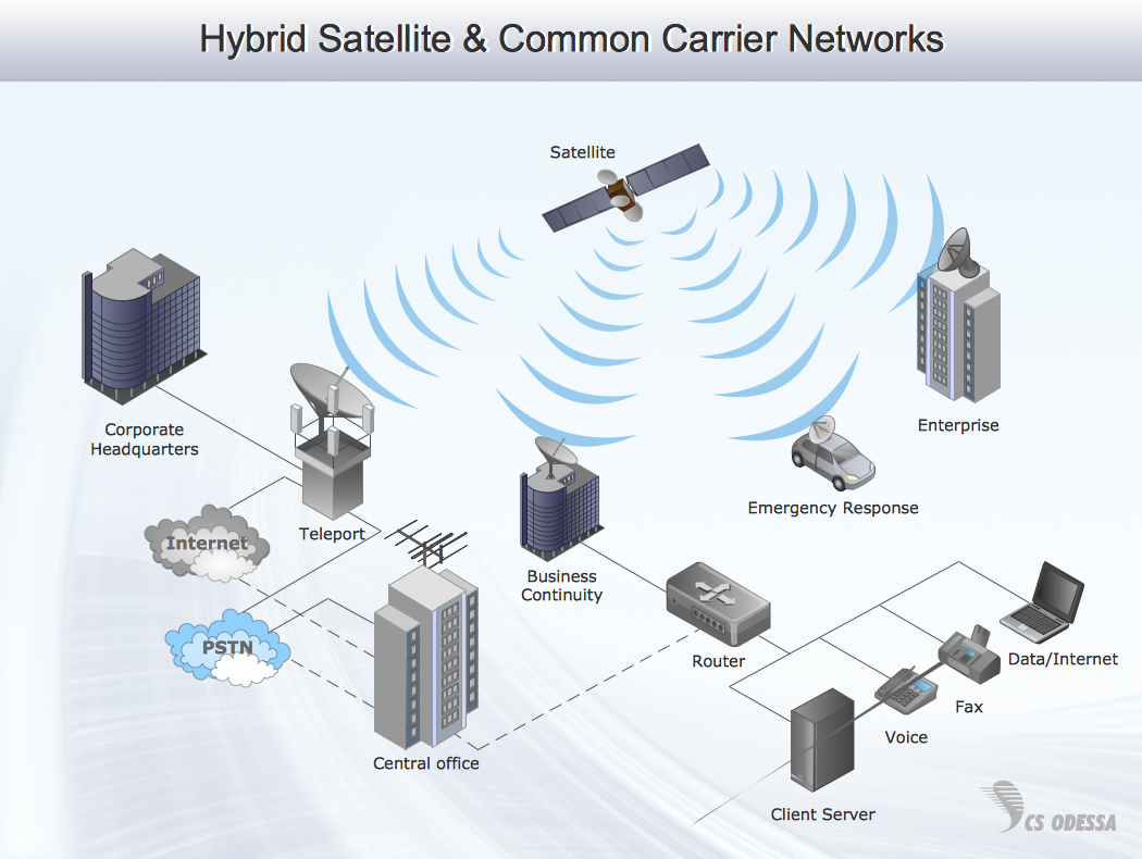
Example 2. Hybrid satellite & common carrier networks — 3D network diagram example
This 3D network diagram sample is created using ConceptDraw DIAGRAM diagramming and vector drawing software enhanced with Computer & Networks solution from ConceptDraw Solution Park.

Example 3. 3D network diagram example
All source documents are vector graphic documents. They are available for reviewing, modifying or converting to a variety of formats (Bitmap Image, PDF, PowerPoint Presentation or MS Visio)
TEN RELATED HOW TO's:
Enterprise systems engineers almost every day face the necessity of network diagrams. We should also take into account that Cisco network design is not only limited to computer networks, but, furthermore, you can design telephone networks and much more. You can build an hierarchical model of your network to get better performance and reliability.
This network diagram represents the utilization of Conceptdraw DIAGRAM for network documentation creation. The diagram shows schematically the structure of a node of a large Internet service provider, which is completed on the basis of Cisco equipment. This diagram was designed using the vector library containing the images of Cisco equipment, supplied with Cisco Network Diagrams solution. In total, the solution has more than ten libraries including more than 500 vector icons of Cisco equipment.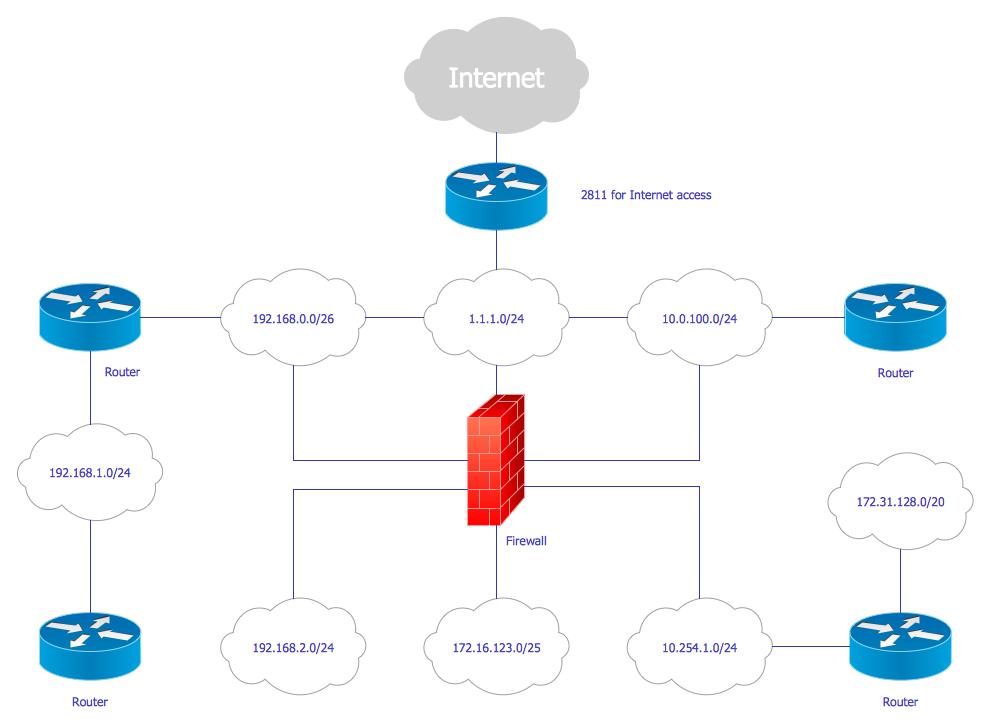
Picture: Cisco Network Design
Related Solution:
Using the predesigned objects, templates and samples of the Computer and Networks Solution for ConceptDraw DIAGRAM you can create your own professional Computer Network Diagrams quick and easy.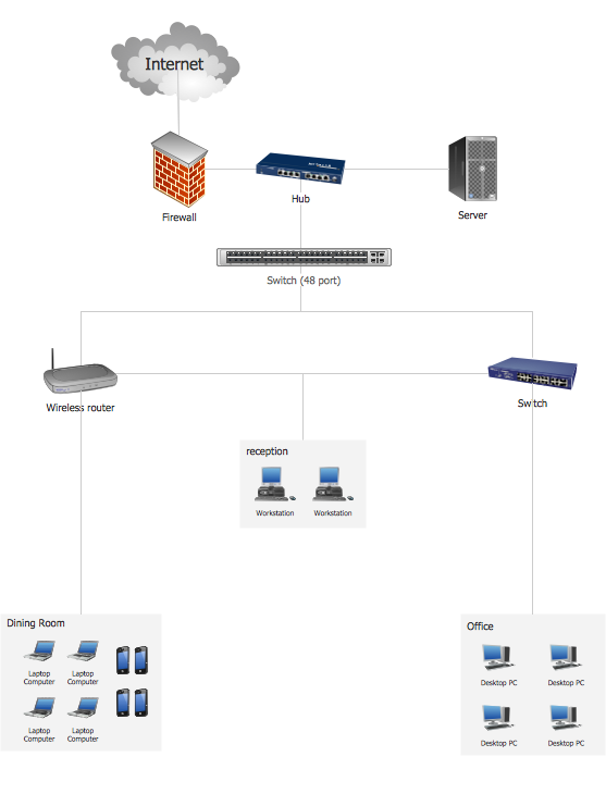
Picture: Hotel Network Topology
Related Solution:
With best content of the ConceptDraw Wireless Network solution that includes more than fifty pre-designed vector stencils network engineers can illustrate the Wireless Network Connection of a buildings.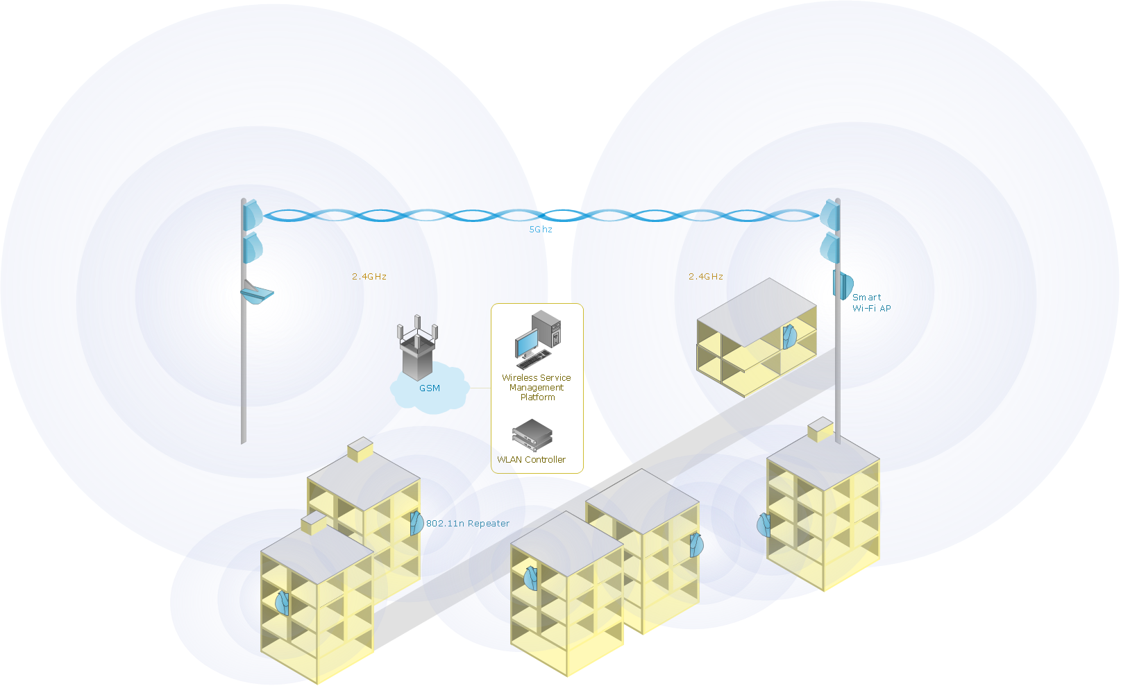
Picture: Wireless Network Connection
Related Solution:
Studying informatics demands knowledge in the area of computer networks as well. The most famous world network, Internet, is an example of wide area network (WAN) topology that connects devices spread on any distance. Unlike other smaller networks that are limited to a building or to a campus, WAN is almost limitless.
This WAN (wide area network) diagram was created in ConceptDraw DIAGRAM. It shows a telecommunication network that covers a large geographical area connecting several settlements. This type of networks is commonly used by business and government institutions. Using the WANs enables them quickly communicate information between remote geographical points. To reproduce this network diagram, you will need the means, provided by ConceptDraw Computer and Network Diagrams solution.
Picture: Wide area network (WAN) topology. Computer and Network Examples
Related Solution:
With best content of the Wireless Network solution that includes more than 10 building pre-designed objects network engineers can illustrate the computer network of a building.
Picture: Illustrate the Computer Network of a Building
Related Solution:
ConceptDraw - Perfect Network Diagramming Software with examples of Backbone Network Diagrams. ConceptDraw Network Diagram is ideal for network engineers and network designers who need to draw Backbone Network diagrams.
Picture: Network Diagram SoftwareBackbone Network
Perfect Network Diagramming Software with examples of LAN Diagrams. ConceptDraw Network Diagram is ideal for network engineers and network designers who need to draw Logical Network diagrams.
Picture: Network Diagram SoftwareLogical Network Diagram
Cabinet is a necessary room in the house. It is very important that the cabinet was comfortable and convenient with elaborated design that dispose to the maximize productive work. The cabinet design is a reflection of the personality, habits and character traits of its owner.
Floor Plans Solution provides templates, samples and wide collection of pre-designed vector stencils that allow you to create the cabinet design plans of any complexity quick, easy and effective.
Picture: Cabinet Design Software
Related Solution:
The metal–oxide–semiconductor field-effect transistor (MOSFET, MOS-FET, or MOS FET) is a type of transistor used for amplifying or switching electronic signals.
Although the MOSFET is a four-terminal device with source (S), gate (G), drain (D), and body (B) terminals, the body (or substrate) of the MOSFET is often connected to the source terminal, making it a three-terminal device like other field-effect transistors. Because these two terminals are normally connected to each other (short-circuited) internally, only three terminals appear in electrical diagrams. The MOSFET is by far the most common transistor in both digital and analog circuits, though the bipolar junction transistor was at one time much more common.
26 libraries of the Electrical Engineering Solution of ConceptDraw DIAGRAM make your electrical diagramming simple, efficient, and effective. You can simply and quickly drop the ready-to-use objects from libraries into your document to create the electrical diagram.
Picture: Electrical Symbols — MOSFET
Related Solution:
Computer and Networks solution provides the libraries with large quantity of predesigned vector objects and the great number of templates and samples that will help design the Cable Networks in a few minutes.
Picture: Cable Network. Computer and Network Examples
Related Solution:
