 Computer Network Diagrams
Computer Network Diagrams solution extends ConceptDraw PRO software with samples, templates and libraries of vector icons and objects of computer network devices and network components to help you create professional-looking Computer Network Diagrams, to plan simple home networks and complex computer network configurations for large buildings, to represent their schemes in a comprehensible graphical view, to document computer networks configurations, to depict the interactions between network's components, the used protocols and topologies, to represent physical and logical network structures, to compare visually different topologies and to depict their combinations, to represent in details the network structure with help of schemes, to study and analyze the network configurations, to communicate effectively to engineers, stakeholders and end-users, to track network working and troubleshoot, if necessary.
Computer Networking Tools List

Personal area (PAN) networks. Computer and Network Examples
 networks. Computer and Network Examples")

UML Diagram Types List

Process Flowchart


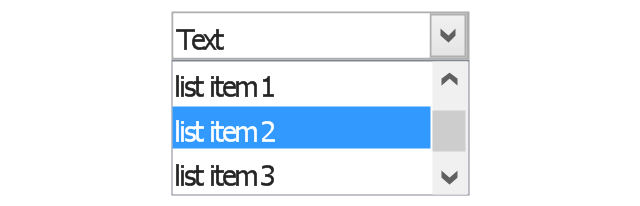
The vector stencils library "Controls" contains 53 icons of Windows 8 controls.
Use it to design graphic user interface (GUI) prototypes of your software applications for Windows 8.
"A graphical control element or widget is an element of interaction in a graphical user interface (GUI), such as a button or a scroll bar. Controls are software components that a computer user interacts with through direct manipulation to read or edit information about an application. ...
Each widget facilitates a specific type of user-computer interaction, and appears as a visible part of the application's GUI as defined by the theme and rendered by the rendering engine. The theme makes all graphical control elements adhere to a unified aesthetic design and creates a sense of overall cohesion. Some widgets support interaction with the user, for example labels, buttons, and check boxes. Others act as containers that group the widgets added to them, for example windows, panels, and tabs." [Graphical control element. Wikipedia]
The design elements example "Controls - Vector stencils library" was created using the ConceptDraw PRO diagramming and vector drawing software extended with the Windows 8 User Interface solution from the Software Development area of ConceptDraw Solution Park.
Balloon

Check box - checked

Check box - unchecked

Radio button - selected

Radio button

Group box
Standard command button

Default command button

Link

Command link - selected

Command link

Command link
Command link 2

Drop-down button with text box
Drop-down button with text box - selected
Drop-down list

List item

List item - selected

Drop-down button with text box 2
Drop-down list 2

Drop-down button

Drop-down button - selected
Combo box
Combo box 2
Combo box with scroller
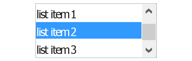
List box
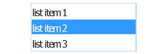
List box with scrollbar
List view
Vertical scroller

Horizontal scroller

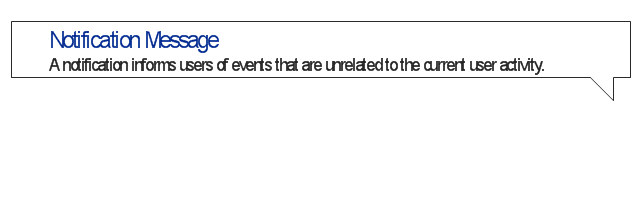
Notification
Options button

Close button

Text label

Progress bar

Search box

Search symbol

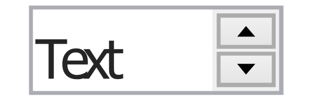
Spin control
Slider - 5 intervals
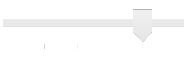
Slider - 10 intervals

Status bar

Start button

Status bar with Start button

Viewed window

Current window state

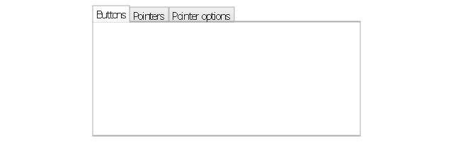
Tab control

Tab control - selected

Tab view page

Tab view
Text box
Text box label

Tooltip

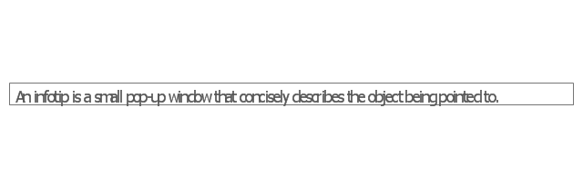
Infotip
HelpDesk
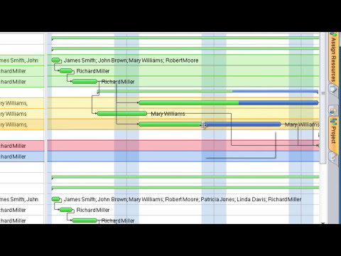
How to Determine what Information to be Displayed in the Project Resource List

UML Diagrams with ConceptDraw PRO

Basic Flowchart Symbols and Meaning


Types of Flowchart - Overview


HelpDesk
How to Create a Custom Filter in ConceptDraw PROJECT for Windows

 Entity-Relationship Diagram (ERD)
Entity-Relationship Diagram (ERD) solution extends ConceptDraw PRO software with templates, samples and libraries of vector stencils from drawing the ER-diagrams by Chen's and crow’s foot notations.
HelpDesk
How to Work with Custom Properties

- Computer Networking Tools List | Find out what amount and type of ...
- Different Types Of Computers List
- Computer Networking Tools List
- UML Diagram Types List | UML Notation | UML Diagrams with ...
- Computer Networking Tools List | Personal area (PAN) networks ...
- Computer Networking Tools List | Computer and Networks Area ...
- Computer Networking Tools List | How to Make Network Diagram ...
- Computer Networking Tools List | ConceptDraw Solution Park ...
- Computer Networking Tools List | ConceptDraw PRO Network ...
- ConceptDraw PRO Network Diagram Tool | Computer Networking ...
- Computer Networking Tools List
- UML Diagram Types List | UML Diagrams with ConceptDraw PRO ...
- Computer Networking Tools List | Network Diagramming Software ...
- Computer Networking Tools List | Active Directory Diagram ...
- UML Diagram Types List | UML Diagrams with ConceptDraw PRO ...
- Computer Networking Tools List | Network Topologies | Active ...
- ConceptDraw PRO Network Diagram Tool | Find out what amount ...
- 4 Level pyramid model diagram - Information systems types | 5 Level ...
- Types Of Computer Network Topologies
- Types Of Computer Network With Diagrams