Swim Lane Flowchart Symbols

Cross-Functional Flowchart (Swim Lanes)

Use flowchart maker of ConceptDraw DIAGRAM enhanced with solutions from ConceptDraw Solution Park to create diagrams to present and explain structures, process flows, logical relationships, networks, design schemes and other visually organized information and knowledge.
Process Flow Diagram Symbols

Taxi Service Data Flow Diagram DFD Example

 Cross-Functional Flowcharts
Cross-functional flowcharts are powerful and useful tool for visualizing and analyzing complex business processes which requires involvement of multiple people, teams or even departments. They let clearly represent a sequence of the process steps, the order of operations, relationships between processes and responsible functional units (such as departments or positions).
Entity Relationship Diagram Symbols

ERD symbols used for professional ERD drawing are collected in libraries from the Entity-Relationship Diagram (ERD) solution for ConceptDraw DIAGRAM.
UML Use Case Diagram Example. Social Networking Sites Project

This sample shows the Facebook Socio-health system and is used at the projection and creating of the social networking sites.
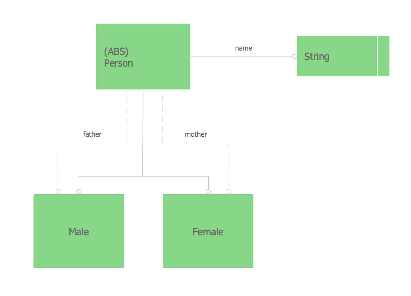
Express-G Diagram
Martin ERD Diagram

- Swim Lane Diagrams | Swim Lane Flowchart Symbols | Cross ...
- DFD - Process of account receivable | Top 5 Android Flow Chart ...
- Audit Flowcharts | Basic Audit Flowchart . Flowchart Examples | Audit ...
- Basic Flowchart Symbols and Meaning | Financial Statement And ...
- Diagram Of Types Of Organizational Structure
- Top 5 Android Flow Chart Apps | Er Diagramm Tool
- Types of Flowcharts | BPMN | Process Flowchart Symbols ...
- Diagramming Software for Design Business Process Diagrams ...
- Business process swim lane diagram BPMN 1.2 - Template | Cross ...
- Payment Flow Diagram For Website
- ERD | Entity Relationship Diagrams, ERD Software for Mac and Win
- Flowchart | Basic Flowchart Symbols and Meaning
- Flowchart | Flowchart Design - Symbols, Shapes, Stencils and Icons
- Flowchart | Flow Chart Symbols
- Electrical | Electrical Drawing - Wiring and Circuits Schematics
- Flowchart | Common Flowchart Symbols
- Flowchart | Common Flowchart Symbols