Made with
ConceptDraw
DIAGRAM 18

Express-G Diagram

Any needed EXPRESS-G Diagrams can be always created with help of the Solutions downloaded from ConceptDraw STORE application and used while working in ConceptDraw DIAGRAM diagramming and drawing software.

One of the data modelling language for product data is EXPRESS, formalized in the ISO Standard as ISO 10303-11. The data models are known to be defining the data objects as well as the relationships among different data objects for a domain of interest. The most standard applications of data models support the processes of developing databases as well as enabling the exchange of data within some area of interest.

The sata models can be specified in a data modelling language, such as EXPRESS, which is defined in the EXPRESS Language Reference Manual. Such EXPRESS data models can be defined in a few ways: graphically and textually. The graphical representation is often known to be better for people to use, but the so called “EXPRESS-G” graphical representation is unable to represent all the details which can be simply formulated in some textual form.

EXPRESS is known to be similar to such programming languages as Pascal, for example. Lots of different datatypes can be defined together within the SCHEMA with algorithmic rules as well as structural constraints. An opportunity of validating a population of datatypes in a formal way is a main feature of EXPRESS data modelling language for product data. Such opportunity can be used for checking for all the algorithmic as well as structural rules.

Being a standard graphical notation used for the information models, EXPRESS-G is known to be a useful companion to the EXPRESS language, used for displaying type and entity definitions, cardinality and relationships. The mentioned graphical notation supports a subset of the EXPRESS language and the advantage of using EXPRESS-G, but EXPRESS, is that the structure of the data model can be represented in a better, meaning a more understandable, manner. Although, there are also the disadvantage of using EXPRESS-G, such as the complexity of the constraints which cannot be properly specified.

There are a few datatypes which EXPRESS can offer, including the specific data type symbols of the EXPRESS-G notation. One of such datatypes is an entity one, which is known to be the most important datatype in EXPRESS, being related in a way of a sub-supertype tree as well as by the attributes. Another example of the datatype is an enumeration one, which is also commonly used as the enumeration values are simple strings such as green, blue and red for an RGB.

Another data type, which is known to be called “defined” as well as a “select” can be also describes, but they seem to be not used as much. In a select data type the selects define a choice between a few different options, such as between different entity types. Sometimes the selects are used which include the defined types. Another datatype is called a “simple” one, such as a “string” one, which is the most often used type. All EXPRESS strings can be of any needed length containing any character (ISO 10646/Unicode).

Such data type as Binary is the only one which is very and very rarely used, covering a few bits, as the size is limited to up to 32 bit. The Logical data type is very similar to the one calls a “Boolean” datatype, where the values of TRUE and FALSE are used, but also the UNKNOWN as well. The so called “number data type” is a supertype of integer and the real ones: EXPRESS integers have any length, although most of the implementations restricted them to a 32 bit value, and an EXPRESS real value has no limits in size and in accuracy. A real value is usually represented by a floating point value of a type double.

The kinds of the so called “aggregation data types” are BAG, SET, ARRAY and LIST. While ARRAY and LIST are ordered, BAG and SET are unordered and a BAG may contain some particular value more than only once, which is not allowed for SET. An ARRAY though is the only aggregate containing the unset members, which is impossible for LIST, SET and BAG. It is important to mention that the members of any aggregate may be of any data type.

There are also a few more things which are important to be mentioned for datatypes, such as the fact the constructed datatypes can be defined within an EXPRESS schema and used for defining the entities as well as specifying the type of the aggregate members and the entity attributes. Any datatypes can be used in a special way for building up more other data types, the complex ones. Thus, it is always possible to define a LIST of an ARRAY of a SELECT of some entities or some other datatypes in case it can make any sense.

An EXPRESS is known to be defining a couple of rules of the way some datatype can be specialized in the future, which is important for the so called “re-declared attributes” of the entities. The GENERIC data types are widely used for procedures, abstract entities and functions.

Express-G Diagram *

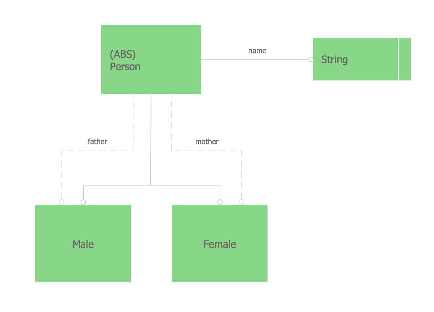
Example 1. Express-G Diagram — Family Scheme

You can always create any needed express diagrams with help of ConceptDraw DIAGRAM diagramming and drawing software as long as you have all the needed tools, such as the design elements previously created by those who know lots about express diagrams as well as all similar drawings. Having the solutions downloaded to your desktop from ConceptDraw STORE after downloading ConceptDraw DIAGRAM from this site can be very beneficial as there will be no need any more to make your own design symbols, but use the existing ones, provided in the mentioned solution.

Apart from having all the needed graphic elements, you can always use the pre-made samples of the express diagrams from the stencil libraries of the mentioned solution. Whatever needs to be created, you can always do it with help of ConceptDraw DIAGRAM diagramming and drawing software where the basic design symbols are, as well as with help of both ConceptDraw DIAGRAM and ConceptDraw STORE as the last mentioned application was developed especially for simplifying work of drawing different diagrams for all the ConceptDraw DIAGRAM users.


NINE RELATED HOW TO's:
A flowchart maker is a software showing the interaction, sequence or organization. It also known as flowchart maker or ConceptDraw DIAGRAM standard supplied with different types of symbol collections: standard symbols, branded set and authored. It used strictly for enhancing scientific or business documents with abstract explanatory pictures. Business graphic applications show a special knowledge representations and include many features for creating schematic pictures. These graphic tools are known as flowchart maker or flowchart maker software.Flowchart Maker *
Picture: Flowchart Maker
Related Solution:
Entity Relationship Diagram (ERD) is an acknowledged method to visualize the logical structure of databases. Using special symbols described in ERD notations you can depict a database of any complexity. The vector graphic ER diagrams produced when using ConceptDraw ERD solution can be used in whitepapers, presentations, datasheets, posters, or any technical materials.What is Entity-Relationship Diagram *
Picture: What is Entity-Relationship Diagram
Related Solution:
When we start to speak about databases, we must always mention database structure visualization. One of the most common ways to do it is to create an entity relationship diagram, and to put appropriate symbols on it. It is important either for database projecting and for its' future maintenance. Entity Relationship Diagram describes data elements and their relationships within a database. There are a set of special symbols that depict each element of an entity relationship diagram. Entities - represents some stable components such as supplier, employee, invoice, client, etc. Relation symbols show how the entities interact. Attributes define characteristics of the relationships. Attributes can be one-to-one or many-to-many. Physical symbols is used in the physical models. They represent items such as fields, tables, types and keys. ERD physical symbols are the building material for the database. Notation lines are used to illustrate the relationships. The most common method is Crow’s Feet notation. You can use ConceptDraw Entity-Relationship Diagram (ERD) solution to represent a database using the Entity-Relationship model.Entity Relationship Diagram Symbols
Picture: Entity Relationship Diagram Symbols
Related Solution:
There are many tools to manage a process or to illustrate an algorithm or a workflow. Flowcharting is one of those tools. However, it may be difficult to show complex processes that require multiple attributes or several people in a simple flowchart, so a cross-functional flowchart would be a solution for that situation. To create such flowchart, group processes and steps to labeled rows or columns, and divide those groups with horizontal or vertical parallel lines. It is worth mentioning that there are different types of cross-functional flowcharts, like opportunity or deployment flowchart. This diagram shows a cross-functional flowchart that was made for a trading process. It contains 14 processes, distributed through 5 lines depicting the participants who interact with the process. Also there are connectors that show the data flow of information between processes. The cross-functional flowchart displays a detailed model of the trading process, as well as all participants in the process and how they interact with each other. The lines in the flowchart indicates the position, department and role of the trading process participants.Cross-Functional Flowchart
Picture: Cross-Functional Flowchart
Related Solution:
This sample was created in ConceptDraw DIAGRAM diagramming and vector drawing software using the Flowcharts solution from the Diagrams area of ConceptDraw Solution Park. This sample shows the Flowchart of the Subprime Mortgage Crisis. This Flowchart describes the decline in housing prices when the housing bubble burst and what it caused on the housing and financial markets. You can also see the Government and Industry responses in this crisis situation.Flowchart on Bank. <br>Flowchart Examples *
Picture: Flowchart on Bank. Flowchart Examples
Related Solution:
ConceptDraw DIAGRAM compatible Mac OS X software extended with powerful Entity-Relationship Diagram (ERD) Solution from the Software Development Area for ConceptDraw Solution Park is one of the famous ER Diagram Programs for Mac. It gives the perfect ability to draw ER diagrams for visually describing databases with Chen's and Crow's Foot notation icons.ER Diagram Programs for Mac *
Picture: ER Diagram Programs for Mac
Related Solution:
Data modelling will help you to study and analyze business processes in your organization for optimization and increase of effectiveness and production.Data modeling with ConceptDraw DIAGRAM  *
Picture: Data modeling with ConceptDraw DIAGRAM
UML Timing Diagram as special form of a sequence diagram are used to explore the behaviors of objects throughout a given period of time.Diagramming Software for Design UML Timing Diagrams *
Picture: Diagramming Software for Design UML Timing Diagrams
Database structures are usually described by ER-diagrams which represents entities as boxes with lines-connections between them. You can create any entity-relationship diagram (ERD) by means of ConceptDraw DIAGRAM using ready-to-use templates and special libraries containing all the needed symbols and shapes. Creating a model for your database from now on can take just a few minutes. ERD (entity relationship diagram) designed to show the logical structure of databases. It intended to depict the relationships between data components (entities). ERDs are a popular tool for software engineers and architects. Using ERD they can manage the every aspect of database design. Also ERD can be used as guidelines for testing and communications before software release. This diagram represents the file reference system of the WordPress web platform. Because entity relationship diagrams have such a broad application area through the prevalence of database technology, it can be applied for a wide range of users.Entity-Relationship Diagram (ERD) <br>with ConceptDraw DIAGRAM  *
Picture: Entity-Relationship Diagram (ERD) with ConceptDraw DIAGRAM
Related Solution:
ConceptDraw
DIAGRAM 18