"A server is a system (software and suitable computer hardware) that responds to requests across a computer network to provide, or help to provide, a network service. Servers can be run on a dedicated computer, which is also often referred to as "the server", but many networked computers are capable of hosting servers. In many cases, a computer can provide several services and have several servers running.
Servers operate within a client-server architecture. Servers are computer programs running to serve the requests of other programs, the clients. Thus, the server performs some tasks on behalf of clients. The clients typically connect to the server through the network but may run on the same computer. In the context of Internet Protocol (IP) networking, a server is a program that operates as a socket listener.
Servers often provide essential services across a network, either to private users inside a large organization or to public users via the Internet. Typical computing servers are database server, file server, mail server, print server, web server, gaming server, application server, or some other kind of server.
Numerous systems use this client / server networking model including Web sites and email services. An alternative model, peer-to-peer networking enables all computers to act as either a server or client as needed." [Server (computing). Wikipedia]
The UML component diagram example "Start server" was created using the ConceptDraw PRO diagramming and vector drawing software extended with the Rapid UML solution from the Software Development area of ConceptDraw Solution Park.
UML component diagram

Components of ER Diagram

Components of ER Diagram
UML Component Diagram


"Component diagram shows components, provided and required interfaces, ports, and relationships between them. This type of diagrams is used in Component-Based Development (CBD) to describe systems with Service-Oriented Architecture (SOA).
Component-based development is based on assumptions that previously constructed components could be reused and that components could be replaced by some other "equivalent" or "conformant" components, if needed.
The artifacts that implement component are intended to be capable of being deployed and re-deployed independently, for instance to update an existing system.
Components in UML could represent:
(1) logical components (e.g., business components, process components), and
(2) physical components (e.g., CORBA components, EJB components, COM+ and .NET components, WSDL components, etc.),
along with the artifacts that implement them and the nodes on which they are deployed and executed. It is anticipated that profiles based around components will be developed for specific component technologies and associated hardware and software environments." [uml-diagrams.org/ component-diagrams.html]
The template "UML component diagram" for the ConceptDraw PRO diagramming and vector drawing software is included in the Rapid UML solution from the Software Development area of ConceptDraw Solution Park.
www.conceptdraw.com/ solution-park/ software-uml
UML component diagram

Local area network (LAN). Computer and Network Examples
 diagram")

Entity Relationship Diagram Examples

UML Component for Bank

Event-Driven Process Chain Diagram Software

UML Class Diagram Example - Apartment Plan

UML Collaboration Diagram. Design Elements

Hotel Network Topology Diagram


Entity Relationship Diagram Symbols

Create UML Diagram

SDL Flowchart Symbols

UML Use Case Diagram Example. Services UML Diagram. ATM system

Banking System

Entity-Relationship Diagram (ERD) with ConceptDraw DIAGRAM
 <br>with ConceptDraw DIAGRAM *")

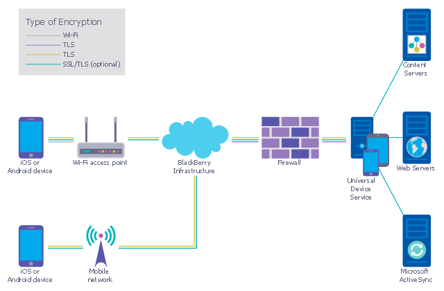
This example was designed on the base of the diagram from the "BYOD Guidance: BlackBerry Secure Work Space" on the website of the UK Communications Electronics Security Group (CESG).
"Secure Work Space (SWS) for iOS and Android is a containerisation, application-wrapping and secure connectivity option that delivers a higher level of control and security to iOS and Android devices, all managed through the BlackBerry Enterprise Service (BES) administration console.
Work space applications are secured and separated from personal applications and data. The work space applications include an integrated email, calendar, and contacts application, an enterprise-level secure browser, and a secure document viewing and editing application.
The work browser allows users to securely browse the organisation’s intranet and the Internet. If the device is lost or the employee leaves the organisation, you can chose to delete only corporate information or all information from the device.
...
Recommended network architecture
The walled garden architecture, shown below, aims to limit the impact of a compromise of an EUD and isolate high risk components from high value components where possible. The enterprise servers installed as part of SWS are high value resources that require suitable protection but are also high risk; they perform complex processing tasks that are more likely to contain exploitable vulnerabilities. These competing priorities make securely placing the servers into an existing network challenging, and organisations that wish to deviate from this architecture below should ensure they understand the risks of doing so."
[cesg.gov.uk/ guidance/ byod-guidance-blackberry-secure-work-space]
The cybersecurity diagram example "Recommended network architecture for BlackBerry SWS" was created using the ConceprDraw PRO software extended with the Network Security Diagrams solution from the Computer and Neworks area of ConceptDraw Solution Park.
Computer security diagram
UML Tool & UML Diagram Examples

- UML component diagram - Start server | Accounting Information ...
- Component Diagram For Email System
- Component Diagram For Email Client System
- Er Daigram For Mail Server Project
- UML component diagram - Start server | UML communication ...
- Entity-Relationship Diagram (ERD) | Components of ER Diagram ...
- Component Diagram For Mail System
- Statechart Diagram For Email Client Server System
- Financial Trade UML Use Case Diagram Example | Components of ...
- Er Diagram Of Email Clients
- State Diagram For E Mail System
- E Mail Daigram
- Data Flow Diagram For Email System
- UML Activity Diagram
- UML component diagram - Start server
- Block Diagram | Functional Block Diagram | Process Flowchart | E ...
- Server hardware - Rack diagram | UML component diagram - Start ...
- Mail Server Erd
- Uml Diagram For Email System
- Email Client System Uml Diagram