Diagramming Software for Design UML Communication Diagrams


UML Collaboration Diagram. Design Elements

Technical Flow Chart

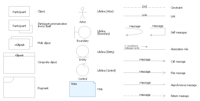
The vector stencils library "UML communication diagrams" contains 23 symbols for the ConceptDraw PRO diagramming and vector drawing software.
"... communication diagrams use the free-form arrangement of objects and links as used in Object diagrams. In order to maintain the ordering of messages in such a free-form diagram, messages are labeled with a chronological number and placed near the link the message is sent over. Reading a communication diagram involves starting at message 1.0, and following the messages from object to object." [Communication diagram. Wikipedia]
The example "Design elements - UML communication diagrams" is included in the Rapid UML solution from the Software Development area of ConceptDraw Solution Park.
UML communication diagram symbols
Local area network (LAN). Computer and Network Examples
 diagram")

 Computer Network Diagrams
Computer Network Diagrams solution extends ConceptDraw DIAGRAM software with samples, templates and libraries of vector icons and objects of computer network devices and network components to help you create professional-looking Computer Network Diagrams, to plan simple home networks and complex computer network configurations for large buildings, to represent their schemes in a comprehensible graphical view, to document computer networks configurations, to depict the interactions between network's components, the used protocols and topologies, to represent physical and logical network structures, to compare visually different topologies and to depict their combinations, to represent in details the network structure with help of schemes, to study and analyze the network configurations, to communicate effectively to engineers, stakeholders and end-users, to track network working and troubleshoot, if necessary.
Diagramming Software for Design UML Collaboration Diagrams

Design Element: Network Layout for Network Diagrams
.png "Design Element: Network Layout<br>for Network Diagrams *")
 Network Layout Floor Plans
Network Layout Floor Plans solution extends ConceptDraw DIAGRAM software functionality with powerful tools for quick and efficient documentation the network equipment and displaying its location on the professionally designed Network Layout Floor Plans. Never before creation of Network Layout Floor Plans, Network Communication Plans, Network Topologies Plans and Network Topology Maps was not so easy, convenient and fast as with predesigned templates, samples, examples and comprehensive set of vector design elements included to the Network Layout Floor Plans solution. All listed types of plans will be a good support for the future correct cabling and installation of network equipment.
Circular Diagram

 Computers and Communications
Computers and communications solution extends ConceptDraw DIAGRAM software with illustration samples, templates and vector stencils libraries with clip art of computers, control devices, communications, technology, Apple machines.
Rack Diagrams

Network Diagramming Software for Design. Cisco Network Diagrams

Network Diagram Software. LAN Network Diagrams. Physical Office Network Diagrams

 ATM UML Diagrams
The ATM UML Diagrams solution lets you create ATM solutions and UML examples. Use ConceptDraw DIAGRAM as a UML diagram creator to visualize a banking system.
Troubleshooting in Wireless Connection

Wireless Network Elements

Process Flow Diagram

 Infographics Area
Solutions of the area What is Infographics from ConceptDraw Solution Park collect templates, samples and vector stencils libraries with design elements for the drawing information graphics.
UML Use Case Diagram. Design Elements

- 8 Elements Of Communication Flow Chart Example
- Flowchart Of Elements Of Communication
- Vasic Flow Of A Venn Diagram Of A Elements Of Communication
- Technical Flow Chart | Flow Chart Symbols | Types of Flowcharts ...
- Components Of Communications Flow Chart
- Process Flowchart | Cross-Functional Flowchart | Basic Flowchart ...
- Design elements - Bank UML communication diagram | Design ...
- Process Flowchart | Basic Flowchart Symbols and Meaning | Flow ...
- Computers and Communications | Design elements - Telecom ...
- Road Transport - Design Elements | Flow chart Example ...
- Design elements - Scrum people | ConceptDraw PRO | Idea ...
- Transport And Communication Diagram On Chart
- Communication medium diagram | Design elements - Transmission ...
- Design elements - UML communication diagrams ...
- UML Collaboration Diagram (UML2.0) | Design elements - Bank ...
- Diagramming Software for Design UML Communication Diagrams ...
- Process Flowchart | Near field communication (NFC). Computer and ...
- Electrical Symbols — Transmission Paths | Digital Communications ...
- Gestures - Vector stencils library | Design elements - Gestures ...
- Transportation Infographics | Spatial infographics Design Elements ...