Booch OOD Diagram

Object-Oriented Development (OOD) Method

UML Flowchart Symbols

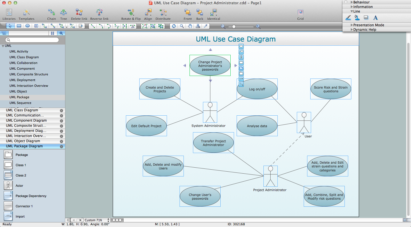
UML Diagram Types List

About UML

Software Diagrams

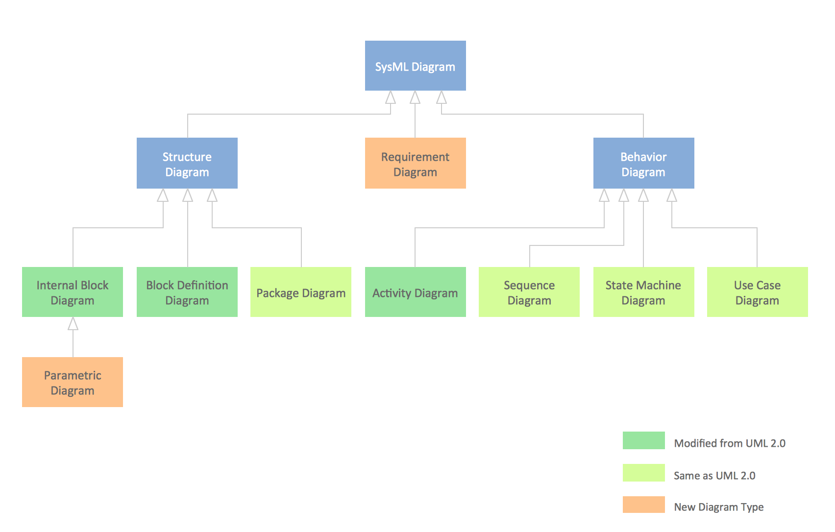
SysML Diagram
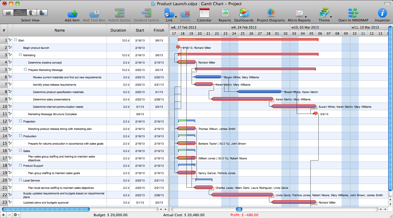
Critical Path Method in ConceptDraw PROJECT
UML for Software Engineers
UML Notation

Yourdon and Coad Diagram

COM and OLE Diagram

SSADM Diagram

IDEF0 Flowchart Symbols

Garrett IA Diagrams with ConceptDraw DIAGRAM

- Booch OOD Diagram | Object -Oriented Development (OOD) Method ...
- Booch OOD Diagram | Examples for OOSE Method | UML Flowchart ...
- Object -Oriented Development (OOD) Method | Booch OOD Diagram ...
- Object Model Diagram Tool
- Booch OOD Diagram | OOSE Method | About UML | Object Oriented ...
- UML Diagram | Object -Oriented Development (OOD) Method | UML ...
- Object -Oriented Development (OOD) Method | UML Diagram | About ...
- Booch OOD Diagram | Examples for OOSE Method | OMT Method ...
- Booch OOD Diagram | Examples for OOSE Method | OOSE Method ...
- Booch OOD Diagram | Examples for OOSE Method | Online Diagram ...
- Object Modeling Using Uml
- Booch OOD Diagram | Program Structure Diagram | OMT Method ...
- Booch OOD Diagram | OMT Method | Object -Oriented Development ...
- Booch OOD Diagram | Software and Database Design with ...
- Object -Oriented Design | Booch OOD Diagram | Coad/Yourdon's ...
- Object Model Uml
- UML Diagram | UML Business Process | Booch OOD Diagram ...
- UML sequence diagram - GET request | UML Class Diagram ...
- UML Diagram | Unified Modeling Language Diagram | UML ...
- Memory Object Diagram | Diagramming Software for Design UML ...