"A piping and instrumentation diagram/ drawing (P&ID) is a diagram in the process industry which shows the piping of the process flow together with the installed equipment and instrumentation. ...
P&IDs play a significant role in the maintenance and modification of the process that it describes. It is critical to demonstrate the physical sequence of equipment and systems, as well as how these systems connect. During the design stage, the diagram also provides the basis for the development of system control schemes, allowing for further safety and operational investigations, such as a Hazard Analysis and Operability Study...
For processing facilities, it is a pictorial representation of:
Key piping and instrument details,
Control and shutdown schemes,
Safety and regulatory requirements,
Basic start up and operational information." [Piping and instrumentation diagram. Wikipedia]
The piping and instrumentation diagram template for the ConceptDraw PRO diagramming and vector drawing software is included in the Chemical and Process Engineering solution from the Engineering area of ConceptDraw Solution Park.
Piping and instrumentation diagram / drawing (P&ID)
-piping-and-instrumentation-diagram-template.png--diagram-flowchart-example.png)
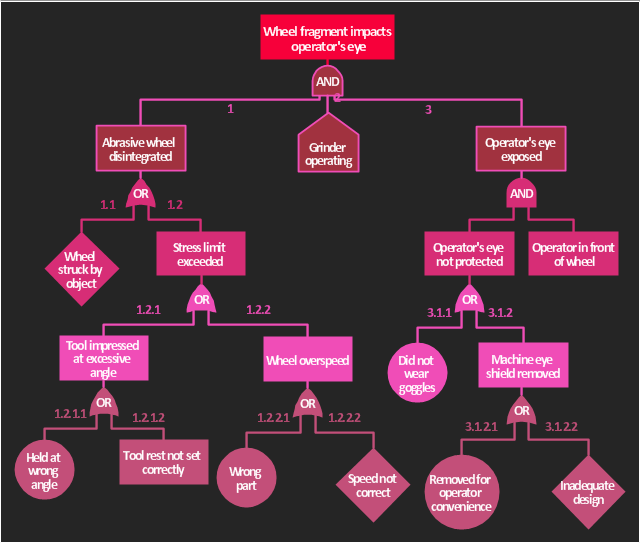
The accident analysis diagram example "Accident analytic tree" was redesigned from the picture 7-14 from the "DOE Workbook. Conducting Accident Investigations. Revision 2."
"Analytic tree analyses are well defined, useful methods that graphically depict, from beginning to end, the events and conditions preceding and immediately following an accident. An analytic tree is a means of organizing information that helps the investigator conduct a deductive analysis of any system (human, equipment, or environmental) to determine critical paths of success and failure. Results from this analysis identify the details and interrelationships that must be considered to prevent the oversights, errors, and omissions that lead to failures. In accident investigations, this type of analysis can consist of both failure paths and success paths, and can lead to neutral, negative, or positive conclusions regarding accident severity.
TIP.
An analytic tree enables the user to:
(1) Systematically identify the possible paths from events to outcome.
(2) Display a graphical record of the analytical process.
(3) Identify management system weaknesses and strengths."
[homer.ornl.gov/ sesa/ corporatesafety/ aip/ docs/ workbook/ Rev2/ chpt7/ chapt7.htm]
The FTA diagram example "Accident analytic tree" was created using the ConceptDraw PRO diagramming and vector drawing software extended with the Fault Tree Analysis Diagrams solution from the Engineering area of ConceptDraw Solution Park.
FTA diagram
Types of Flowchart - Overview


CORRECTIVE ACTIONS PLANNING. Involvement Matrix


 Audit Flowcharts
Audit flowcharts solution extends ConceptDraw PRO software with templates, samples and library of vector stencils for drawing the audit and fiscal flow charts.
The Building Blocks Used in EPC Diagrams
")
Decision Making

Organogram Software

Probability Quality Control Tools

Applications

 Sales Flowcharts
The Sales Flowcharts solution lets you create and display sales process maps, sales process workflows, sales steps, the sales process, and anything else involving sales process management.
PROBLEM ANALYSIS. Root Cause Analysis Tree Diagram

 Seven Management and Planning Tools
Seven Management and Planning Tools solution extends ConceptDraw PRO and ConceptDraw MINDMAP with features, templates, samples and libraries of vector stencils for drawing management mind maps and diagrams.
HelpDesk
How To Create Root Cause Analysis Diagram Using ConceptDraw Office

Root Cause Tree Diagram

- Accident analytic tree - FTA diagram | Causal Tree Investigation ...
- Accident analytic tree - FTA diagram | FTA diagram - Hazard ...
- Failure Investigation Flow Chart
- Fault Tree Analysis Diagrams | PROBLEM ANALYSIS. Root Cause ...
- Diagram Related Investigation In Auditing
- Flow Chart Of Failure Investigation
- Accident analytic tree - FTA diagram | Fault Tree Analysis Diagrams ...
- CCTV Network Example | How to Create a CCTV Diagram in ...
- Accident analytic tree - FTA diagram | Decision Making ...
- Affinity Diagram | Affinity diagram - Implementing continuous ...
- Fault Tree Diagram | PROBLEM ANALYSIS. Root Cause Analysis ...
- Piping and instrumentation diagram template | Piping and ...
- Fault Tree Analysis Diagrams | Accident analytic tree - FTA diagram ...
- How to Create a Fault Tree Analysis Diagram (FTD) in ConceptDraw ...
- Accident analytic tree - FTA diagram | Fault Tree Diagram | Fault ...
- Accident analytic tree - FTA diagram | SYSML | IDEF0 Diagrams ...
- How To Create Root Cause Analysis Diagram Using ConceptDraw ...
- Entity Relationship Diagram - ERD - Software for Design Crows Foot ...
- Accident analytic tree - FTA diagram | Fault Tree Analysis Diagrams ...