How To use House Electrical Plan Software


Cafe Floor Plan. Cafe Floor Plan Examples

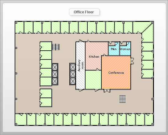
How To Create Floor Plans

HelpDesk
Accounting Information Systems Flowchart Symbols

Workflow Flowchart Symbols

Gane Sarson Diagram

Family Emergency Plan

The vector stencils library "Network layout floorplan" contain 34 symbol icons for drawing computer network floor plans and communication equipment and cabling layouts.
"Networking hardware may also be known as network equipment or computer networking devices. Units which are the last receiver or generate data are called hosts or data terminal equipment.
All these terms refer to devices facilitating the use of a computer network. Specifically, they mediate data in a computer network. ...
Typically, networking hardware includes gateways, routers, network bridges, switches, hubs, and repeaters. But it also includes hybrid network devices such as multilayer switches, protocol converters, bridge routers, proxy servers, firewalls, network address translators, multiplexers, network interface controllers, wireless network interface controllers, modems, ISDN terminal adapters, line drivers, wireless access points, networking cables and other related hardware.
The most common kind of networking hardware today is a copper-based Ethernet adapter because of its standard inclusion on most modern computer systems. Wireless networking has, however, become increasingly popular, especially for portable and handheld devices.
Other hardware prevalent in computer networking includes data center equipment (such as file servers, database servers and storage areas), network services (such as DNS, DHCP, email, etc.) as well as devices which assure content delivery." [Networking hardware. Wikipedia]
The shapes example "Design elements - Network layout floorplan" was created using the ConceptDraw PRO diagramming and vector drawing software extended with the Network Layout Floor Plans solution from the Computer and Networks area of ConceptDraw Solution Park.
Network layout floor plan symbols

Swim Lane Flowchart Symbols

Fire Exit Plan. Building Plan Examples

Building Drawing Design Element: Shipping and Receiving

Home area networks (HAN). Computer and Network Examples
")

Business diagrams & Org Charts with ConceptDraw PRO


How To Draw Building Plans

HelpDesk
How to Create a Data Flow Diagram
 example")
- Network Layout Floor Plans | Design elements - Network layout ...
- Architectural Drawing Symbols Column Slab
- How To use Furniture Symbols for Drawing Building Plan | How to ...
- Accounting Flowchart Symbols | Building Plan Software. Building ...
- Electrical Drawing Software and Electrical Symbols | Data Flow ...
- Network Layout Floor Plans | Ethernet cable layout | Home ...
- Mechanical Drawing Symbols | ERD Symbols and Meanings | Data ...
- How To Create Restaurant Floor Plan in Minutes | How to Import ...
- Data Flow Diagram Symbols . DFD Library | Basic Flowchart ...
- Mechanical Drawing Symbols | Mechanical Drawing Software | CAD ...
- How To use House Electrical Plan Software | Database Flowchart ...
- Data Flow Diagram (DFD) | Design elements - Bathroom | DFD ...
- Mechanical Drawing Symbols | How To use House Electrical Plan ...
- Cisco Buildings. Cisco icons , shapes, stencils and symbols | How To ...
- Data Flow Diagram Symbols . DFD Library | Anyone Have an ERD ...
- Kinds Of Wall Symbol In Floor Plan
- Drawing Symbol Of Sink
- Network Data Drop Symbol
- Network Layout Floor Plans | Design elements - Network layout ...
- How To use House Electrical Plan Software | Design elements ...