Electrical Symbols, Electrical Diagram Symbols

Electrical Symbols — Resistors

Electrical Symbols — Transformers and Windings

Electrical Symbols — Rotating Equipment

"The symbols and conventions used in welding documentation are specified in national and international standards such as ISO 2553 Welded, brazed and soldered joints -- Symbolic representation on drawings and ISO 4063 Welding and allied processes -- Nomenclature of processes and reference numbers. The US standard symbols are outlined by the American National Standards Institute and the American Welding Society and are noted as "ANSI/ AWS".
In engineering drawings, each weld is conventionally identified by an arrow which points to the joint to be welded. The arrow is annotated with letters, numbers and symbols which indicate the exact specification of the weld. In complex applications, such as those involving alloys other than mild steel, more information may be called for than can comfortably be indicated using the symbols alone. Annotations are used in these cases." [Symbols and conventions used in welding documentation. Wikipedia]
The example chart "Elements of welding symbol" is redesigned using the ConceptDraw PRO diagramming and vector drawing software from the Wikipedia file: Elements of a welding symbol.PNG.
[en.wikipedia.org/ wiki/ File:Elements_ of_ a_ welding_ symbol.PNG]
The diagram example "Elements location of a welding symbol" is contained in the Mechanical Engineering solution from the Engineering area of ConceptDraw Solution Park.
Welding joint symbol chart

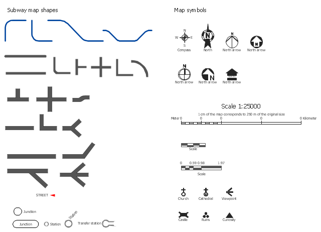
The vector stencils library Map symbols contains 19 icons for labeling the maps using the ConceptDraw PRO diagramming and vector drawing software.
The vector stencils library Subway map contains 41 shapes for creating the subway (tube, metro) maps using the ConceptDraw PRO.
"The various features shown on a map are represented by conventional signs or symbols. For example, colors can be used to indicate a classification of roads. Those signs are usually explained in the margin of the map, or on a separately published characteristic sheet.
Some cartographers prefer to make the map cover practically the entire screen or sheet of paper, leaving no room "outside" the map for information about the map as a whole. These cartographers typically place such information in an otherwise "blank" region "inside" the map -- cartouche, map legend, title, compass rose, bar scale, etc. In particular, some maps contain smaller "sub-maps" in otherwise blank regions—often one at a much smaller scale showing the whole globe and where the whole map fits on that globe, and a few showing "regions of interest" at a larger scale in order to show details that wouldn't otherwise fit." [Map. Wikipedia]
The example "Design elements - Subway map, Map symbols" is included in the Directional Maps solution from the Maps area of ConceptDraw Solution Park.
Map symbols
Process Flow Diagram Symbols

How To use Appliances Symbols for Building Plan

Electrical Symbols — Qualifying

The vector stencils library Initiation and annunciation contains 9 symbols of Fire Alarm Control Panel (FACP) or Fire Alarm Control Unit (FACU) elements, triggering devices, audible alarm systems, timers, security control equipment, and recording devices.
"A Fire Alarm Control Panel (FACP), or Fire Alarm Control Unit (FACU), is the controlling component of a Fire Alarm System. The panel receives information from environmental sensors designed to detect changes associated with fire, monitors their operational integrity and provides for automatic control of equipment, and transmission of information necessary to prepare the facility for fire based on a predetermined sequence. The panel may also supply electrical energy to operate any associated sensor, control, transmitter, or relay. There are four basic types of panels: coded panels, conventional panels, addressable panels, and multiplex systems." [Fire alarm control panel. Wikipedia]
Use the shapes library Initiation and annunciation to draw layout floor plans, communications schematics and wiring diagrams of security systems using the ConceptDraw PRO diagramming and vector drawing software.
The design elements library Initiation and annunciation is included in the Security and Access Plans solution from the Building Plans area of ConceptDraw Solution Park.
Initiation and annunciation symbols

Organic Chemistry Symbols

How To Create Emergency Plans and Fire Evacuation

Electrical Symbols — Integrated Circuit

Technical Drawing Software

Electrical Symbols — MOSFET

Simple & Fast Diagram Software


Chemistry Symbols and Meanings

- Conventional Symbols In Engineering Drawing On Bearings
- Mechanical Drawing Symbols | Home Electrical Plan | Electrical ...
- Conventional Symbol Of Drawing
- Conventional Symbols In Engineering
- Conventional Signs And Symbols In Civil Engineering Pdf
- Draw The Conventional Signs And Symbols Of Building And ...
- Mechanical Drawing Symbols | Technical Drawing Software ...
- Conventional Symbol Of Bearing In Mechanical Drawing
- Blueprint Software | Mechanical Drawing Symbols | Classroom ...
- Conventional Symbols In Technical Drawing
- Conventional Symbols Used In Landscape Drawings
- Mechanical Drawing Symbols | Home Electrical Plan | Process Flow ...
- Conventional Signs And Symbols Of Engineering Drawings And ...
- Mechanical Drawing Software | Electrical Symbols — Qualifying ...
- Conventional Representation Draw Welding Symbol
- Basic Flowchart Symbols and Meaning | Process Flowchart ...
- Bearings - Vector stencils library | Mechanical Drawing Symbols ...
- Basic Flowchart Symbols and Meaning | Design elements - Subway ...
- Conventional Symbol Of Spring