UML Component Diagram Example - Online Shopping

Diagramming Software for Design UML Component Diagrams


UML Component Diagram

UML Deployment Diagram Example - ATM System UML diagrams

Online Diagram Tool

Example of DFD for Online Store (Data Flow Diagram)


Banking System

How to create your UML Diagram

UML Class Diagram Example for GoodsTransportation System

UML Collaboration Diagram (UML2.0)
 *")
UML Tool & UML Diagram Examples

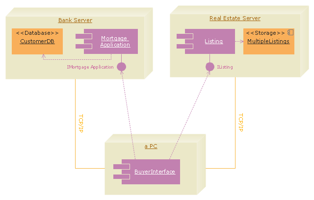
"A real estate transaction is the process whereby rights in a unit of property (or designated real estate) is transferred between two or more parties, e.g. in case of conveyance one party being the seller(s) and the other being the buyer(s). It can often be quite complicated due to the complexity of the property rights being transferred, the amount of money being exchanged, and government regulations. Conventions and requirements also vary considerably among different countries of the world and among smaller legal entities (jurisdictions).
In more abstract terms, a real estate transaction, like other financial transactions, causes transaction costs. To identify and possibly reduce these transaction costs, the Organization for Economic Co-operation and Development (OECD) addressed the issue through a study commissioned by the European Commission, and through a research action.
The mentioned research action ‘Modelling Real Property Transactions’ investigated methods to describe selected transactions in a formal way, to allow for comparisons across countries / jurisdictions. Descriptions were performed both using a more simple format, a Basic Use Case template, and more advanced applications of the Unified Modelling Language. Process models were compared through an ontology-based methodology, and national property transaction costs were estimated for Finland and Denmark, based on the directions of the United Nations System of National Accounts." [Real estate transaction. Wikipedia]
The UML deployment diagram example "Real estate transactions" was created using the ConceptDraw PRO diagramming and vector drawing software extended with the Rapid UML solution from the Software Development area of ConceptDraw Solution Park.
UML deployment diagram
UML Deployment Diagram. Diagramming Software for Design UML Diagrams

UML Deployment Diagram. Design Elements

Interaction Overview Diagram

State Diagram Example — Online Store

UML Composite Structure Diagram

UML Class Diagram Example - Apartment Plan

UML Deployment Diagram

UML Component for Bank

- Deployment Diagram For Online Payment System
- Online Payment System Component Diagram
- UML deployment diagram - Template | Deployment Diagram For ...
- Uml Deployment Diagram For Electricity Online Billing System
- UML Component Diagram Example - Online Shopping | UML Class ...
- ATM UML Diagrams | Component Diagram For Online Money Transfer
- Component Diagram On Electricity Bill
- UML Component Diagram Example - Online Shopping | UML ...
- Component Diagram For Online Feedback System
- UML component diagram example
- Component And Deployment Diagrams For Customer Support System
- E Payment System Block Diagram
- Component And Deployment Diagram For Online Money Transfer
- Uml Diagram For Online Feedback System
- Use Case Diagram For Online Payment System
- UML use case diagram - Banking system | UML Deployment ...
- ATM UML Diagrams | Online Money Transfer Through E Banking ...
- Component And Deployment Diagram For Taxi Service Management
- Deployment Diagram For Credit Card Processing System