Interior Design. Machines and Equipment — Design Elements

Mechanical Drawing Symbols

Mechanical Engineering

Piping and Instrumentation Diagram Software

The vector stencils library "Machines and equipment" contains 24 symbols of industrial machines and equipment.
Use the design elements library "Machines and equipment" for drawing plant interior design plans, manufacturing equipment layouts and factory floor plans using the ConceptDraw PRO diagramming and vector drawing software.
"Manufacturing is the production of goods for use or sale using labor and machines, tools, chemical and biological processing, or formulation. The term may refer to a range of human activity, from handicraft to high tech, but is most commonly applied to industrial production, in which raw materials are transformed into finished goods on a large scale.
Modern manufacturing includes all intermediate processes required for the production and integration of a product's components. Some industries, such as semiconductor and steel manufacturers use the term fabrication instead.
The manufacturing sector is closely connected with engineering and industrial design." [Manufacturing. Wikipedia]
The shapes library "Machines and equipment" is included in the Plant Layout Plans solution from the Building Plans area of ConceptDraw Solution Park.
Machines and equipment symbols

Electrical Symbols — Composite Assemblies

Electrical Symbols — Power Sources

 Computer Network Diagrams
Computer Network Diagrams solution extends ConceptDraw DIAGRAM software with samples, templates and libraries of vector icons and objects of computer network devices and network components to help you create professional-looking Computer Network Diagrams, to plan simple home networks and complex computer network configurations for large buildings, to represent their schemes in a comprehensible graphical view, to document computer networks configurations, to depict the interactions between network's components, the used protocols and topologies, to represent physical and logical network structures, to compare visually different topologies and to depict their combinations, to represent in details the network structure with help of schemes, to study and analyze the network configurations, to communicate effectively to engineers, stakeholders and end-users, to track network working and troubleshoot, if necessary.
 SYSML
SYSML
The SysML solution helps to present diagrams using Systems Modeling Language; a perfect tool for system engineering.
Types of Flowcharts


Electrical Symbols — Switches and Relays

Workflow Application

Process Flowchart


 Floor Plans
Construction, repair and remodeling of the home, flat, office, or any other building or premise begins with the development of detailed building plan and floor plans. Correct and quick visualization of the building ideas is important for further construction of any building.
Electrical Symbols — Rotating Equipment

The vector stencils library "Instruments" contains 72 symbols of control instruments and measuring devices: meters and gauges, and callouts, text boxes, and inserts.
Use these shapes to create annotated process flow diagrams (PFD), flow control, manufacturing processes, and distribution system diagrams.
"Process control is an engineering discipline that deals with architectures, mechanisms and algorithms for maintaining the output of a specific process within a desired range.
Process control is extensively used in industry and enables mass production of continuous processes such as oil refining, paper manufacturing, chemicals, power plants and many other industries. Process control enables automation, with which a small staff of operating personnel can operate a complex process from a central control room." [Process control. Wikipedia]
The example "Design elements - Instruments" was created using the ConceptDraw PRO diagramming and vector drawing software extended with the Chemical and Process Engineering solution from the Engineering area of ConceptDraw Solution Park.
Process control instrument symbols

 People
This solution extends ConceptDraw DIAGRAM software with samples, templates and libraries of vector clipart for drawing the People illustrations. Use it to make professional-looking documents, presentations and websites illustrated with color scalable vector c
The vector stencils library "HR professions" contains 81 professions pictograms.
Use this HR icon set to draw your HR flowcharts, workflow diagrams, process charts and infographics with the ConceptDraw PRO diagramming and vector drawing software.
The HR pictograms library "HR professions" is included in the HR Flowcharts solution from the Management area of ConceptDraw Solution Park.
Accountant

Actor

Administrator

Announcer

Archaeologist

Architect

Artist

Baker

Banker

Bellboy

Biologist

Bookkeeper

Builder

Businessman

Businesswoman

Call center operator

Cameraman

Carpenter

Cashier

Chef

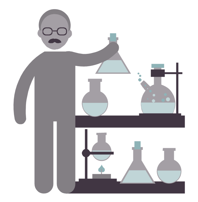
Chemist

Cleaner

Clerk

Consultant

Cook

Dentist

Director

Dispatcher

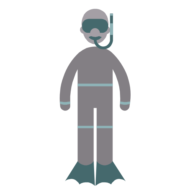
Diver
Doctor

Driver

Electrical engineer

Engineer

Environmental engineer

Farmer

Firefighter

Fisherman

Florist

Gardener

Graphic designer

Guide

Hairdresser

Lawyer

Librarian

Machine operator

Manager

Miner

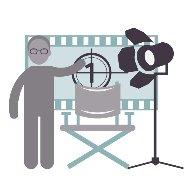
Movie director
Musician

Nuclear engineer

Nurse

Pharmacist

Photographer

Pilot

Pizza delivery man

Policeman

Postman

Presenter

Programmer

Psychologist

Reporter

Sailor

Scientist
Secretary

Security guard

Security officer

Seller

Shop assistant

Soldier

Stewardess

Surgeon

System administrator

Systems engineer

Tailor

Teacher

Technical support representative

Waiter

Waitress

Watchman

Worker

Writer

Model Based Systems Engineering

 Safety and Security
Safety and security solution extends ConceptDraw DIAGRAM software with illustration samples, templates and vector stencils libraries with clip art of fire safety, access and security equipment.
- Process Flow Diagram Symbols | Flow Chart Symbols | Design ...
- Chemical and Process Engineering | Technical Drawing Software ...
- Design elements - Process annotations | Technical Flow Chart ...
- Chemical engineering - Vector stencils library | Design elements ...
- Laboratory equipment - Vector stencils library | Design elements ...
- How to Draw a Chemical Process Flow Diagram | Design elements ...
- Process Engineering | Process Flowchart | Process Flow Diagram ...
- Draw And Label A Diagram Of A Hydraulic Press
- Process Flow Diagram Symbols | Process Flow Diagram | Technical ...
- Chemical engineering - Vector stencils library | Drawing a Nature ...
- HR professions - Vector stencils library | Design elements ...
- Process Flow Diagram Symbols
- Interior Design Machines and Equipment - Design Elements | Piping ...
- Design elements - Machines and equipment | Machines and ...
- Mechanical Engineering | Mechanical Drawing Software ...
- Chemical and Process Engineering | Chemical engineering - Vector ...
- Design elements - Industrial equipment | Design elements ...
- Mechanical Drawing Symbols | Mechanical Engineering | Process ...
- | Technical Drawing Software | Interior Design . Machines and ...
- Process Flow Diagram Symbols | Chemical and Process ...