Entity Relationship Diagram Examples


Sign Making Software

 School and Training Plans
School and Training Plans solution enhances ConceptDraw DIAGRAM functionality with extensive drawing tools, numerous samples and examples, templates and libraries of classroom design elements for quick and professional drawing the School and Training plans, School Floor plans, Classroom Layout, Classroom Seating chart, Lecture Room plans of any complexity. Each offered classroom seating chart template is a real help for builders, designers, engineers, constructors, as well as teaching personnel and other teaching-related people in drawing Classroom Seating charts and Training Room layouts with ConceptDraw DIAGRAM classroom seating chart maker.
How to Draw an Effective Flowchart

 Active Directory Diagrams
Active Directory Diagrams solution significantly extends the capabilities of ConceptDraw DIAGRAM software with special Active Directory samples, convenient template and libraries of Active Directory vector stencils, common icons of sites and services, icons of LDPA elements, which were developed to help you in planning and modelling network structures and network topologies, in designing excellently looking Active Directory diagrams, Active Directory Structure diagrams, and Active Directory Services diagram, which are perfect way to visualize detailed structures of Microsoft Windows networks, Active Directory Domain topology, Active Directory Site topology, Organizational Units (OU), and Exchange Server organization.
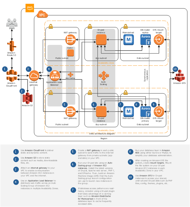
This AWS architecture diagram example shows the deployment of Drupal architecture on the Amazon Web Services Cloud.
This AWS architecture sample was designed on the base of the diagram "Drupal on AWS" from the Amazon Web Services website. [aws.amazon.com/ ru/ quickstart/ architecture/ drupal/ ]
"This reference architecture provides a set of YAML templates for deploying Drupal on AWS using Amazon Virtual Private Cloud (Amazon VPC), Amazon Elastic Compute Cloud (Amazon EC2), Auto Scaling, Elastic Load Balancing (Application Load Balancer), Amazon Relational Database Service (Amazon RDS), Amazon ElastiCache, Amazon Elastic File System (Amazon EFS), Amazon CloudFront, Amazon Route 53, Amazon Certificate Manager (Amazon ACM) with AWS CloudFormation." [github.com/ aws-samples/ aws-refarch-drupal]
The Amazon Web Services diagram example "Drupal Hosting on AWS" was designed using ConceptDraw PRO software extended with AWS Architecture Diagrams solution from Computer and Networks area of ConceptDraw Solution Park.
AWS architecture diagram
Active Directory Network. Computer and Network Examples


Campus Area Networks (CAN). Computer and Network Examples
. <br>Computer and Network Examples *")
Diagram of a Basic Computer Network. Computer Network Diagram Example

The vector stencils library "Active Directory" contains 20 symbols of Active Directory elements for drawing AD network diagrams. It helps network and system administrators to visualize Microsoft Windows Active Directory structures for network design, installation and maintainance.
"An Active Directory structure is an arrangement of information about objects. The objects fall into two broad categories: resources (e.g., printers) and security principals (user or computer accounts and groups). Security principals are assigned unique security identifiers (SIDs).
Each object represents a single entity - whether a user, a computer, a printer, or a group - and its attributes. Certain objects can contain other objects. An object is uniquely identified by its name and has a set of attributes - the characteristics and information that the object represents - defined by a schema, which also determines the kinds of objects that can be stored in Active Directory.
The schema object lets administrators extend or modify the schema when necessary. However, because each schema object is integral to the definition of Active Directory objects, deactivating or changing these objects can fundamentally change or disrupt a deployment. Schema changes automatically propagate throughout the system. Once created, an object can only be deactivated - not deleted. Changing the schema usually requires planning. Sites are implemented as a set of well-connected subnets." [Active Directory. Wikipedia]
The AD symbols example "Active Directory - Vector stencils library" was created using the ConceptDraw PRO diagramming and vector drawing software extended with the Active Directory Diagrams solution from the Computer and Networks area of ConceptDraw Solution Park.
www.conceptdraw.com/ solution-park/ active-directory-diagrams
Domain
Computer
User
Group

Container
Print queue
Contact

Organizational unit
Policy
Volume
Generic object

Site
Site link
Site link bridge
Server
NTDS site settings
IP subnet
Certificate template

Licensing site

Connection

Entity Relationship Software

Active Directory

UML Deployment Diagram


Organizational Structure Total Quality Management

UML for Bank

 Presentation Clipart
Presentation design elements solution extends ConceptDraw DIAGRAM software with slide samples, templates and vector stencils libraries with design elements of presentation symbols, arrows, callouts, backgrounds, borders and frames, title blocks.
Microsoft Azure

 AWS Architecture Diagrams
AWS Architecture Diagrams with powerful drawing tools and numerous predesigned Amazon icons and AWS simple icons is the best for creation the AWS Architecture Diagrams, describing the use of Amazon Web Services or Amazon Cloud Services, their application for development and implementation the systems running on the AWS infrastructure. The multifarious samples give you the good understanding of AWS platform, its structure, services, resources and features, wide opportunities, advantages and benefits from their use; solution’s templates are essential and helpful when designing, description and implementing the AWS infrastructure-based systems. Use them in technical documentation, advertising and marketing materials, in specifications, presentation slides, whitepapers, datasheets, posters, etc.
TQM Software — Build Professional TQM Diagrams

- Entity Relationship Diagram Examples
- Active Directory Diagram | Certificate Maker Download
- AWS Architecture Diagrams | AWS Simple Icons for Architecture ...
- AWS Architecture Diagrams | How to Create an AWS Architecture ...
- Social Media Response | Data Flow Diagram (DFD) | AWS Security ...
- Active Directory diagram - Asymmetric encryption | Active Directory ...
- Active Directory Diagrams | Design elements - AWS Security, Identity ...
- Aircraft examples | Aerospace and Transport | HVAC Plans ...
- AWS Simple Icons for Architecture Diagrams | Design elements ...
- AWS Architecture Diagrams | Design elements - AWS Security ...
- AWS Architecture Diagrams | AWS Security, Identity and ...
- Active Directory diagram - Asymmetric encryption | Active Directory ...
- Aircraft examples | Aerospace and Transport | Design elements ...
- Active Directory Domain Services | Network Diagram Examples ...
- Design elements - Aircraft | Fishbone Diagram | Computer and ...
- Internet - Vector stencils library | Cloud round icons - Vector stencils ...
- AWS Architecture Diagrams | Azure Architecture | Computer Network ...
- AWS Architecture Diagrams | Design elements - AWS Security ...
- Mobile app security | Azure Architecture | AWS Architecture ...
- Cisco Network Topology. Cisco icons, shapes, stencils and symbols ...