How To use House Electrical Plan Software


Electrical Symbols, Electrical Diagram Symbols

Home Electrical Plan

The vector stencils library "Qualifying" contains 56 qualifying symbols of radiation, polarity, phase, windings, wire, ground, connection, connector, coaxial, electret.
Use these signs to annotate or specify characteristics of objects in electrical drawings, electronic schematics, circuit diagrams, electromechanical drawings, and wiring diagrams, cabling layout diagrams.
"An electrical drawing, is a type of technical drawing that shows information about power, lighting, and communication for an engineering or architectural project. Any electrical working drawing consists of "lines, symbols, dimensions, and notations to accurately convey an engineering's design to the workers, who install the electrical system on the job".
A complete set of working drawings for the average electrical system in large projects usually consists of:
(1) A plot plan showing the building's location and outside electrical wiring.
(2) Floor plans showing the location of electrical systems on every floor.
(3) Power-riser diagrams showing panel boards.
(4) Control wiring diagrams.
(5) Schedules and other information in combination with construction drawings.
Electrical drafters prepare wiring and layout diagrams used by workers who erect, install, and repair electrical equipment and wiring in communication centers, power plants, electrical distribution systems, and buildings." [Electrical drawing. Wikipedia]
The signs example "Design elements - Qualifying" was drawn using the ConceptDraw PRO diagramming and vector drawing software extended with the Electrical Engineering solution from the Engineering area of ConceptDraw Solution Park.
Qualifying symbols

This cafe electrical floor plan sample shows the outlet and switch layout.
"An electrical drawing, is a type of technical drawing that shows information about power, lighting, and communication for an engineering or architectural project. Any electrical working drawing consists of "lines, symbols, dimensions, and notations to accurately convey an engineering's design to the workers, who install the electrical system on the job".
A complete set of working drawings for the average electrical system in large projects usually consists of:
(1) A plot plan showing the building's location and outside electrical wiring.
(2) Floor plans showing the location of electrical systems on every floor.
(3) Power-riser diagrams showing panel boards.
(4) Control wiring diagrams.
(5) Schedules and other information in combination with construction drawings.
Electrical drafters prepare wiring and layout diagrams used by workers who erect, install, and repair electrical equipment and wiring in communication centers, power plants, electrical distribution systems, and buildings." [Electrical drawing. Wikipedia]
The outlet and switch layout example "Cafe electrical floor plan" was created using the ConceptDraw PRO diagramming and vector drawing software extended with the Electric and Telecom Plans solution from the Building Plans area of ConceptDraw Solution Park.
Outlet and switch layout

Wiring Diagrams with ConceptDraw DIAGRAM

The vector stenvils library "Outlets" contains 57 symbols of electrical outlets for drawing building interior design, electrical floor plans and layouts of AC power plugs and sockets.
"AC power plugs and sockets are devices that allow electrically operated equipment to be connected to the primary alternating current (AC) power supply in a building. Electrical plugs and sockets differ in voltage and current rating, shape, size and type of connectors. The types used in each country are set by national standards, some of which are listed in the IEC technical report TR 60083, Plugs and socket-outlets for domestic and similar general use standardized in member countries of IEC.
Plugs and sockets for portable appliances started becoming available in the 1880s, to replace connections to light sockets with easier to use wall-mounted outlets. A proliferation of types developed to address the issues of convenience and protection from electric shock. Today there are approximately 20 types in common use around the world, and many obsolete socket types are still found in older buildings. Co-ordination of technical standards has allowed some types of plugs to be used over wide regions to facilitate trade in electrical appliances, and for the convenience of travellers and consumers of imported electrical goods. Some multi-standard sockets allow use of several different types of plugs; improvised or unapproved adapters between incompatible sockets and plugs may not provide the full safety and performance of an approved adapter." [AC power plugs and sockets. Wikipedia]
The example "Design elements - Outlets" was created using the ConceptDraw PRO diagramming and vector drawing software extended with the Electric and Telecom Plans solution from the Building plans area of ConceptDraw Solution Park.
Electrical outlet symbols

The vector stencils library "Electrical and telecom" contains 83 symbols of electrical and telecommunication equipment for electrical drawings and wiring diagrams of buildings, communication centers, power plants and electrical distribution systems.
"An electrical drawing, is a type of technical drawing that shows information about power, lighting, and communication for an engineering or architectural project." [Electrical drawing. Wikipedia]
Use the design elements library "Electrical and telecom" to design your own electrical drawings, plot plans of the building outside electrical wiring, floor plans with electrical and telecommunication systems layout, power-riser diagrams with panel boards, control wiring diagrams and cabling layout schemes, reflected ceiling plans and lighting panels layouts using the ConceptDraw PRO diagramming and vector drawing software.
The shapes library "Electrical and telecom" is included in the Electric and Telecom Plans solution from the Building Plans area of ConceptDraw Solution Park.
Electrical and telecom symbols

Building Plans with ConceptDraw DIAGRAM

The vector stencils library "Switches" contains 25 symbols of electrical and light switches and breakers.
"In electrical engineering, a switch is an electrical component that can break an electrical circuit, interrupting the current or diverting it from one conductor to another.
The most familiar form of switch is a manually operated electromechanical device with one or more sets of electrical contacts, which are connected to external circuits.
A switch may be directly manipulated by a human as a control signal to a system, ... or to control power flow in a circuit, such as a light switch. Automatically operated switches can be used to control the motions of machines, for example, to indicate that a garage door has reached its full open position or that a machine tool is in a position to accept another workpiece. Switches may be operated by process variables such as pressure, temperature, flow, current, voltage, and force, acting as sensors in a process and used to automatically control a system. For example, a thermostat is a temperature-operated switch used to control a heating process. A switch that is operated by another electrical circuit is called a relay." [Switch. Wikipedia]
Use the design elements library "Switches" for drawing light switches layouts, electrical and telecommunication equipment floor plans for building design and construction using the ConceptDraw PRO diagramming and vector drawing software.
The shapes library "Switches" is included in the Electric and Telecom Plans solution from the Building Plans area of ConceptDraw Solution Park.
Electrical switch symbols

Daisy Chain Network Topology

 Electrical Engineering
This solution extends ConceptDraw DIAGRAM.9.5 (or later) with electrical engineering samples, electrical schematic symbols, electrical diagram symbols, templates and libraries of design elements, to help you design electrical schematics, digital and analog
Local area network (LAN). Computer and Network Examples
 diagram")

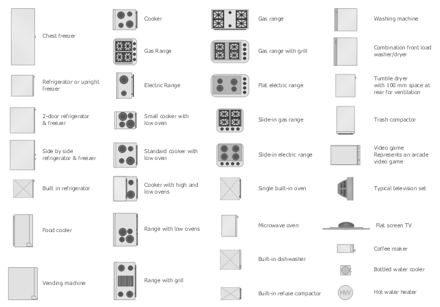
The vector stencils library Appliances contains 36 symbols of kitchen appliances, laundry appliances, stoves, cooking appliances, and laundry equipment.
Use the shapes library Appliances to draw equipment layouts and interior design floor plans of kitchens, laundry rooms, utility rooms using the ConceptDraw PRO diagramming and vector drawing software.
"Home appliances are electrical/ mechanical machines which accomplish some household functions, such as cooking or cleaning. Home appliances can be classified into:
Major appliances, or White goods;
Small appliances, or Brown goods;
Consumer electronics, or Shiny goods.
White goods/ major appliances comprise major household appliances and may include: air conditioner, dishwasher, clothes dryer, drying cabinet, freezer, refrigerator, kitchen stove, water heater, washing machine, trash compactor, microwave ovens and induction cookers.
Brown goods/ small appliances are typically small household electrical entertainment appliances such as: TV sets, CD and DVD players, camcorders, still cameras, clocks, alarm clocks, video game consoles, HiFi and home cinema, telephones and answering machines.
Consumer electronics (abbreviated CE) are electronic equipment intended for everyday use, most often in entertainment, communications and office productivity. Main products include radio receivers, television sets, MP3 players, video recorders, DVD players, digital cameras, camcorders, personal computers, video game consoles, telephones and mobile phones." [Home appliance. Wikipedia]
The design elements library Appliances is provided by the Floor Plans solution from the Building Plans area of ConceptDraw Solution Park.
The vector stencils library "Cable TV" contains 64 symbols of cable TV network equipment.
Use these shapes for drawing CATV system design floor plans, network topology diagrams, wiring diagrams and cabling layout schemes in the ConceptDraw PRO diagramming and vector drawing software.
The vector stencils library "Cable TV" is included in the Electric and Telecom Plans solution from the Building Plans area of ConceptDraw Solution Park.
Output Directional Tap 1

Output Directional Tap 2

Output Directional Tap 3

Output Directional Tap 4

Output Directional Tap 5

2-way Splitter

3-way Splitter

4-way Splitter

AC Power Block

Bond

Down Guy

Building Guy and Anchor

Rock Guy with Anchor

Down Guy with Anchor

Pole-to-Pole Guy

Sidewalk Down Guy with Anchor

Sidewalk Down Guy

Slack Span Messenger Wire

Tensioned Messenger Wire w/out cable

Tensioned Messenger Wire

Ground

Joint Usage (Power & Telephone Pole)
-cable-tv---vector-stencils-library.png--diagram-flowchart-example.png)
Joint Usgae Pole with Transformer

Strut

Tree Guy with Anchor

Push Brace (smaller pole in actual relative position)
-cable-tv---vector-stencils-library.png--diagram-flowchart-example.png)
Extension Arm

Built CATV Pole

Proposed CATV Pole

Directional Tap 1

Directional Tap 2

Manhole

Telephone Pole

Riser Pole

Vault Handheld

Fixed Equalizer

Fixed Flat Attenuators

Other Supporting Structures

Pedestal - Underground Routing

Power Pole

Direct Buried Underground Routing

Duct Line Underground Routing

Line Terminations

2-Way Optical Splice Location

3-Way Optical Splice Location

4-Way Optical Splice Location

> 4-Way Optical Splice Location

Optical Amplifier

Cable AC Power Combiner

Optical Fiber Cable

Optical Connector

Wavelength Demultiplexer

Wavelength Multiplexer

Optical Transmitter

Optical Transmitter

Optical Node

Optical Splitter

Headend (Signal Processing)
-cable-tv---vector-stencils-library.png--diagram-flowchart-example.png)
Node

Primary Hub

Secondary Hub

Coaxial Splice

Power Supply

Variable Equalizer

 Chemical and Process Engineering
This chemical engineering solution extends ConceptDraw DIAGRAM.9.5 (or later) with process flow diagram symbols, samples, process diagrams templates and libraries of design elements for creating process and instrumentation diagrams, block flow diagrams (BFD
Network Diagram Software Home Area Network

The vector stencils library "Electrical circuits" contains 49 element symbols of electrical and electronic devices, including ignitors, starters, transmitters, circuit protectors, transducers, radio and audio equipment.
Use it for drawing electronic circuit diagrams and electrical schematics in the ConceptDraw PRO diagramming and vector drawing software extended with the Electrical Engineering solution from the Engineering area of ConceptDraw Solution Park.
www.conceptdraw.com/ solution-park/ engineering-electrical
Ground

Equipotentiality

Igniter plug

Junction

Chassis

Chassis 2

Capacitor

Variable capacitor

Capacitor 2

Variable capacitor 2

Antenna

Antenna 2

Circuit breaker

Fuse

Fuse 2

Alarm fuse

Alarm fuse 2

Circular generic component

Rectangular generic component

Transducer

Capacitive transducer

Non-capacitive transducer

Recording pickup head

Reproducing pickup head

Positive pulse

Negative pulse

Alternating pulse

Saw tooth

Positive step function

Negative step function

Explosive squib

Sensing link squib

Squib ignitor

Unspecified material

Solid material

Semiconducting material

Liquid

Insulating material

Gas

Electret

Surge protector

Multigap surge protector

Valve surge protector

Electrolytic surge protector

Carbon block surge protector

Protective gap surge protector

Sphere gap surge protector

Horn gap surge protector

Circuit breaker

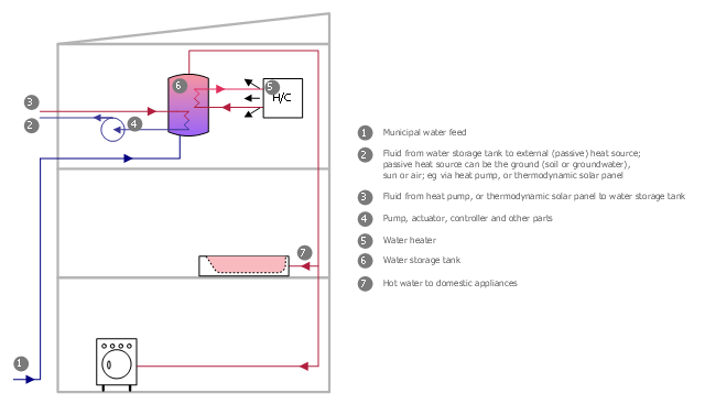
This plumbing and piping plan sample was designed on the base of the Wikimedia Commons file: Active Indirect Water Heater Diagram.svg.
[commons.wikimedia.org/ wiki/ File:Active_ Indirect_ Water_ Heater_ Diagram.svg]
This file is licensed under the Creative Commons Attribution-Share Alike 3.0 Unported license. [creativecommons.org/ licenses/ by-sa/ 3.0/ deed.en]
"Water heating is a thermodynamic process that uses an energy source to heat water above its initial temperature. Typical domestic uses of hot water include cooking, cleaning, bathing, and space heating. In industry, hot water and water heated to steam have many uses.
Domestically, water is traditionally heated in vessels known as water heaters, kettles, cauldrons, pots, or coppers. These metal vessels that heat a batch of water do not produce a continual supply of heated water at a preset temperature. Rarely, hot water occurs naturally, usually from natural hot springs. The temperature varies based on the consumption rate, becoming cooler as flow increases.
Appliances that provide a continual supply of hot water are called water heaters, hot water heaters, hot water tanks, boilers, heat exchangers, geysers, or calorifiers. These names depend on region, and whether they heat potable or non-potable water, are in domestic or industrial use, and their energy source. In domestic installations, potable water heated for uses other than space heating is also called domestic hot water (DHW).
Fossil fuels (natural gas, liquefied petroleum gas, oil), or solid fuels are commonly used for heating water. These may be consumed directly or may produce electricity that, in turn, heats water. Electricity to heat water may also come from any other electrical source, such as nuclear power or renewable energy. Alternative energy such as solar energy, heat pumps, hot water heat recycling, and geothermal heating can also heat water, often in combination with backup systems powered by fossil fuels or electricity." [Water heating. Wikipedia]
The plumbing plan example "Active indirect water heater diagram" was created using the ConceptDraw PRO diagramming and vector drawing software extended with the Plumbing and Piping Plans solution from the Building Plans area of ConceptDraw Solution Park.
Plumbing and piping plan
The vector stencils library "Transformers and windings" contains 29 element symbols of transformers, windings, couplers, metering devices, transductors, magnetic cores, chokes, and a variometer.
Use it to design the electromechanical device schematics and electronic circuit diagrams in the ConceptDraw PRO diagramming and vector drawing software extended with the Electrical Engineering solution from the Engineering area of ConceptDraw Solution Park.
www.conceptdraw.com/ solution-park/ engineering-electrical
Coaxial choke

Transductor

Saturating transformer

1-phase induction voltage regulator

Triplex induction voltage regulator

Induction voltage regulator

Current transformer 2

Current transformer 3

Potential transformer 2

Potential transformer with 3 windings

Outdoor metering device

Linear coupler

Magnetic core, 1 line

Magnetic core, 2 lines

Choke

Variometer

Air-core transformer

Magnetic-core transformer

Air-core transformer, 1 winding adjustable

Magnetic-core transformer, 1 winding adjustable

Air-core transformer, 2 windings adjustable

Magnetic-core transformer, 2 windings adjustable

Air-core transformer, mutual inductor

Magnetic-core transformer, mutual inductor

Transformer 2

Adjustable transformer, 1 winding

Adjustable transformer, mutual inductor

Current transformer 1

Potential transformer

- Electrical Building Installation Layout And Wiring Diagram In Pdf
- Building Electrical Installation Design Pdf
- Sample School Building Electrical Wiring Diagram
- Electrical Installation Symbols Of Building
- Cafe electrical floor plan | Network Layout Floor Plans | Working ...
- How To use House Electrical Plan Software | Electrical Installation ...
- Biulding Electrical Installation Pdf
- Power Installation Drawings Show What
- Plumbing and Piping Plans | HVAC Plans | Sanitery Instalation
- Design Of Building Electrical Lighting Installation Layout Pdf
- Design Of Building Electrical Lighting Installation Layout Pdf
- Importance Of Plans And Layout Of Electrical Installation
- Electrical Installation Planning Preparing And Designing
- Electrical Diagram Installation
- How To use House Electrical Plan Software | Electrical Design ...
- HVAC Plans | Plant Layout Plans | Computer and Networks Area ...
- How to Create a Residential Plumbing Plan | Plumbing and Piping ...
- Electric and Telecom Plans | Electrical Drawing Of A 3 Bedroom Flat
- Electrical Working Drawings
- Electric and Telecom Plans | Building Electrical Plan