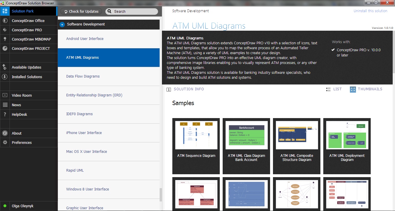
UML Deployment Diagram Example - ATM System UML diagrams

This sample shows the work of the ATM (Automated Teller Machine) banking system that is used for service and performing of the banking transactions using ATMs. System engineers can use comprehensive UML diagrams solution.
UML Deployment Diagram. Design Elements

ConceptDraw has 393 vector stencils in the 13 libraries that helps you to start using software for designing your own UML Diagrams. You can use the appropriate stencils of UML notation from UML Deployment library.
UML Deployment Diagram
Use ConceptDraw DIAGRAM with UML deployment diagram templates, samples and stencil library from Rapid UML solution to model the physical deployment of artifacts on nodes of your software system.

UML Diagram

Create unified modeling language (UML) diagrams with ConceptDraw.
UML Collaboration Diagram. Design Elements

ConceptDraw has 393 vector stencils in the 13 libraries that helps you to start using software for designing your own UML Diagrams. You can use the appropriate stencils of UML notation from UML Collaboration library with 36 objects
UML Component Diagram Example - Online Shopping

This sample shows the concept of the online shopping and is used for the understanding of the online shopping processes, of the online shops working processes, for projection and creating of the online stores.
Design Elements for UML Diagrams

Diagramming Software for Design UML Package Diagrams

Yourdon and Coad Diagram

ATM Solutions
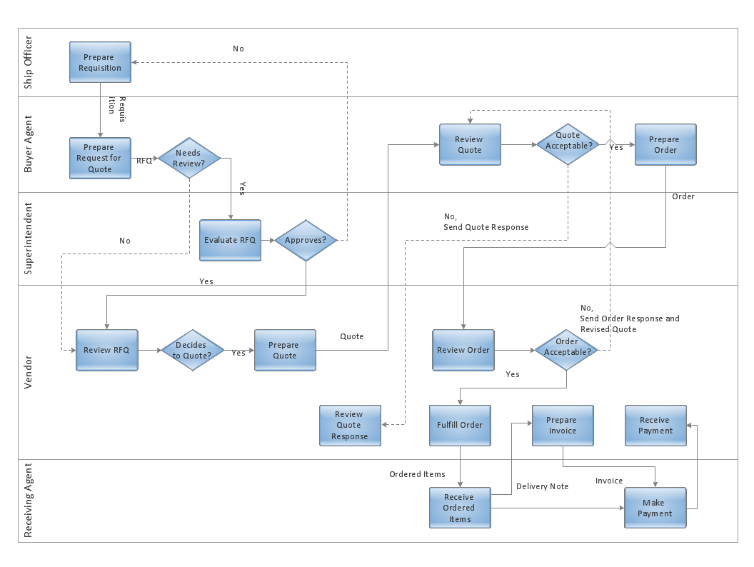
Cross-Functional Flowcharts in ConceptDraw
UML Activity Diagram

Use ConceptDraw DIAGRAM diagramming and vector drawing software enhanced with Rapid UML solution from ConceptDraw Solution Park to create your own UML activity diagrams that show the business and operational workflows of components and overall flow of control in your systems. Such software provides coloring UML diagrams for various purposes and simplifying work of the engineers.
 Entity-Relationship Diagram (ERD)
Entity-Relationship Diagram (ERD) solution extends ConceptDraw DIAGRAM software with templates, samples and libraries of vector stencils from drawing the ER-diagrams by Chen's and crow’s foot notations.
Bank Sequence Diagram

 Entity-Relationship Diagram (ERD)
An Entity-Relationship Diagram (ERD) is a visual presentation of entities and relationships. That type of diagrams is often used in the semi-structured or unstructured data in databases and information systems. At first glance ERD is similar to a flowch
- UML Deployment Diagram Example
- UML Deployment Diagram Example - ATM System UML diagrams ...
- UML Deployment Diagram Example - ATM System UML diagrams ...
- UML Deployment Diagram Example - ATM System UML diagrams ...
- UML Deployment Diagram Example - ATM System UML diagrams
- UML Deployment Diagram Example - ATM System UML diagrams ...
- Atm System Notations Deployment Diagram
- Component And Deployment Diagram For Library Management
- UML Deployment Diagram Example - ATM System UML diagrams ...
- UML Component Diagram Example - Online Shopping | UML ...
- UML Deployment Diagram Example - ATM System UML diagrams ...
- UML Deployment Diagram Example - ATM System UML diagrams ...
- UML Deployment Diagram Example - ATM System UML diagrams ...
- UML Deployment Diagram Example - ATM System UML diagrams ...
- UML Deployment Diagram Example - ATM System UML diagrams ...
- UML Deployment Diagram Example - ATM System UML diagrams ...
- Package Diagram With Example In Banking System Model
- UML Deployment Diagram Example - ATM System UML diagrams ...
- UML Deployment Diagram . Diagramming Software for Design UML ...
- Deployment Diagram For Library Management
- ERD | Entity Relationship Diagrams, ERD Software for Mac and Win
- Flowchart | Basic Flowchart Symbols and Meaning
- Flowchart | Flowchart Design - Symbols, Shapes, Stencils and Icons
- Flowchart | Flow Chart Symbols
- Electrical | Electrical Drawing - Wiring and Circuits Schematics
- Flowchart | Common Flowchart Symbols
- Flowchart | Common Flowchart Symbols