Mechanical Drawing Symbols

UML State Machine Diagram.Design Elements

This technical drawing shows the machine parts assembly using joining by threaded fasteners.
"Assembling (joining of the pieces) is done by welding, binding with adhesives, riveting, threaded fasteners, or even yet more bending in the form of a crimped seam. Structural steel and sheet metal are the usual starting materials for fabrication, along with the welding wire, flux, and fasteners that will join the cut pieces. As with other manufacturing processes, both human labor and automation are commonly used. The product resulting from fabrication may be called a fabrication. Shops that specialize in this type of metal work are called fab shops. The end products of other common types of metalworking, such as machining, metal stamping, forging, and casting, may be similar in shape and function, but those processes are not classified as fabrication." [Metal fabrication. Wikipedia]
This mechanical engineering drawing example was designed using ConceptDraw PRO diagramming and vector drawing software extended with Mechanical Engineering solution from Engineering area of ConceptDraw Solution Park.

 Engineering
This solution extends ConceptDraw PRO v9.4 with the ability to visualize industrial systems in electronics, electrical, chemical, process, and mechanical engineering.
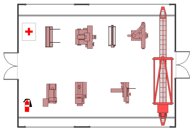
The example "Factory layout floor plan" shows manufacturing machines and equipment in the plant warehouse.
"A factory (previously manufactory) or manufacturing plant is an industrial site, usually consisting of buildings and machinery, or more commonly a complex having several buildings, where workers manufacture goods or operate machines processing one product into another.
Most modern factories have large warehouses or warehouse-like facilities that contain heavy equipment used for assembly line production. Large factories tend to be located with access to multiple modes of transportation, with some having rail, highway and water loading and unloading facilities." [Factory. Wikipedia]
The example "Factory layout floor plan" was created using the ConceptDraw PRO diagramming and vector drawing software extended with the Plant Layout Plans solution from the Building Plans area of ConceptDraw Solution Park.
Industrial equipment layout
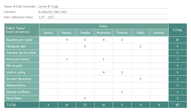
This check sheet example was redesigned from the Wikimedia Commons file: Check sheet for motor assembly.svg. [commons.wikimedia.org/ wiki/ File:Check_ sheet_ for_ motor_ assembly.svg]
This file is licensed under the Creative Commons Attribution-Share Alike 3.0 Unported license. [creativecommons.org/ licenses/ by-sa/ 3.0/ deed.en]
"The check sheet is a form (document) used to collect data in real time at the location where the data is generated. The data it captures can be quantitative or qualitative. When the information is quantitative, the check sheet is sometimes called a tally sheet.
The check sheet is one of the so-called Seven Basic Tools of Quality Control. ...
Kaoru Ishikawa identified five uses for check sheets in quality control:
- To check the shape of the probability distribution of a process
- To quantify defects by type
- To quantify defects by location
- To quantify defects by cause (machine, worker)
- To keep track of the completion of steps in a multistep procedure (in other words, as a checklist)" [. Wikipedia]
The example "Check sheet for motor assembly" was created using the ConceptDraw PRO software extended with the Seven Basic Tools of Quality solution from the Quality area of ConceptDraw Solution Park.
Check sheet example
Used Solutions
Quality
>
UML Notation

Process Flowchart


UML Timing Diagram, Design Elements

Cross-Functional Flowchart


UML Class Diagram. Design Elements

UML Composite Structure Diagram. Design Elements

UML Component Diagram. Design Elements
")

Diagramming Software for Design UML Component Diagrams
")
UML Interaction Overview Diagram. Design Elements

- Assembly Of Machine Parts In Engineering Graphics
- Technical drawing - Machine parts assembling | How to Create a ...
- Assembly Diagrams Of Machines
- Machine Drawing Assembly Diagram
- Assembly Of Some Parts Related To Mechanical Engineers
- Technical drawing - Machine parts assembling | Mechanical ...
- Engi Mech Draw Machine Assembly
- Plant Layout Plans | Factory layout floor plan | Emergency Plan ...
- Machine Drawing Assembly Solutions
- Sample Machine Assembly Diagram
- Mechanical Engineering Drawing Machine Assembly
- Solution For Assembly Machine Drawing
- Machine Drafting Assembly Digrame
- Assembly Machine Diagrams
- Plant Layout Of Factory Machines
- Assembly Chart Sample
- Engineering Drawing Symbols On Machine
- Machine Assembly Drawing Software
- Mechanical Engineering Machine Assembly
- Fire and Emergency Plans | Interior Design Machines and ...