Diagramming Software for Design UML Collaboration Diagrams


Interaction Overview Diagram

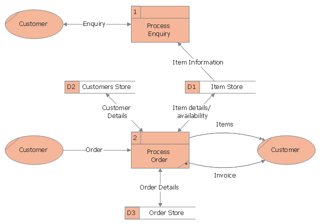
Example of DFD for Online Store (Data Flow Diagram)


Program Structure Diagram

Diagramming Software for Design UML Interaction Overview Diagrams

Diagramming Software for Design UML Communication Diagrams

This DFD sample was designed on the base of Wikimedia Commons file: DFD0.png.
"This is a Level 0 Data Flow Diagram for the fictional company "AvisonPlay.com".
[commons.wikimedia.org/ wiki/ File:DFD0.png]
This file is licensed under the Creative Commons Attribution-Share Alike 3.0 Unported license. [creativecommons.org/ licenses/ by-sa/ 3.0/ deed.en]
The DFD example "Data flow diagram - Order" was designed using ConceptDraw PRO software extended with Сlassic Business Process Modeling solution from Business Processes area of ConceptDraw Solution Park.
Business process modeling diagram
Data Flow Diagram

 Data Flow Diagrams (DFD)
Data Flow Diagrams solution extends ConceptDraw DIAGRAM software with templates, samples and libraries of vector stencils for drawing the data flow diagrams (DFD).
Data Flow Diagram Process

Data Flow Diagram Symbols. DFD Library

UML Collaboration Diagram. Design Elements

 Classic Business Process Modeling
The ConceptDraw DIAGRAM software enhanced with Classic Business Process Modeling solution is a powerful flowchart maker and professional business process modeling software with extensive choice of drawing tools, libraries with wide variety of ready-to-use vector objects that are more than sufficient for modeling the business processes and for instant creation variety of diagram types: Control Flow Diagram, Swimlane Diagram, Business Process Modeling Diagram, Functional Flow Block Diagram, Data Flow Diagram. It is ideal for business analysts, developers, as well as for managers and regular users. The samples included to Classic Business Process Modeling solution allow to uncover the solution’s power and to answer qualitatively on how to create a flowchart or to model the business processes with help of diagrams and schemes.
Data Flow Diagram Examples

Banking System

Data Flow Diagrams

Data Flow Diagram (DFD)
 *")
Data Flow Diagram Model

Communication Diagram UML2.0 / Collaboration UML1.x

UML Class Diagram. Design Elements

- Data Flow Diagram (DFD) | Data Flow Diagram Software | Basic ...
- Data Flow Diagram Level 0 1 2 For Library Management System
- Healthcare Management Workflow Diagrams | Data Flow Diagram ...
- Data Flow Diagram Symbols. DFD Library | Example of DFD for ...
- Data Flow Diagram Symbols. DFD Library | Pyramid Chart Examples ...
- Process Flowchart | Data Flow Diagram Level 0 1 2 Examples ...
- Difference Between Context Diagram And Level 0 Dfd
- Data Flow Diagram Level 0 1 2 Example On Banks
- Flowcharts | Level 0 Dfd For Accounts Receivable
- Data Flow Diagram Process | Structured Systems Analysis and ...
- Data Flow Diagram For Hotel Management System Level 0
- Program Structure Diagram | IDEF0 Diagrams | Data Flow Diagram ...
- Context Diagram And Level 0 Dfd
- Example of DFD for Online Store ( Data Flow Diagram ) DFD ...
- Data Flow Diagram (DFD) | Flow chart Example. Warehouse ...
- DFD Library System | Cross-Functional Flowchart | UML Use Case ...
- DFD - Process of account receivable | Data Flow Diagrams (DFD ...
- Dfd Level 0 For Healthcare System
- Dfd Level 0 Diagram For Bus Reservation System
- Data Flow Diagrams (DFD) | Level 1 Dfd Of Hotel Management System