Work Flow Process Chart

Basic Flowchart Symbols and Meaning


Powerful Drawing Feature for Creating Professional Diagrams
Horizontal Flowchart
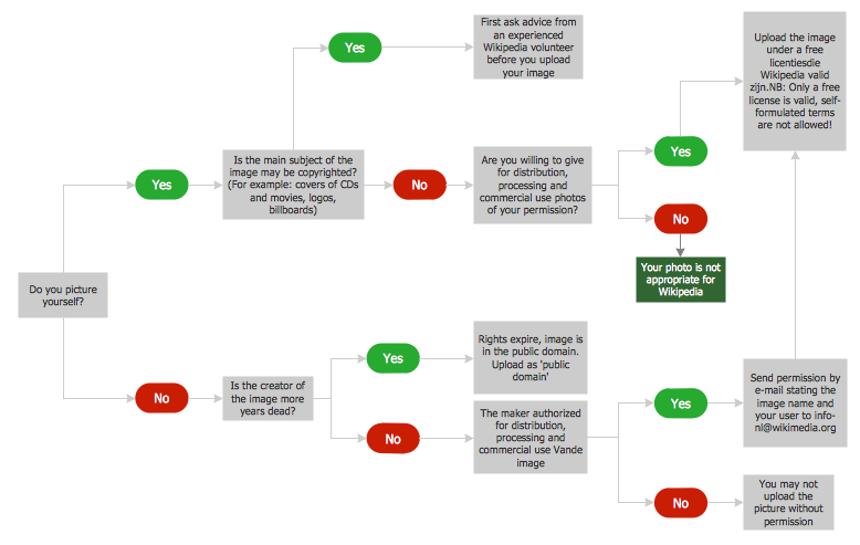
A Flowchart is a graphically representation of the process, algorithm or the step-by-step solution of the problem. The Flowcharts have one or more starting and ending points. The geometric figures on the Flowcharts represent the steps of the process and are connected with arrows that show the sequence of the actions.
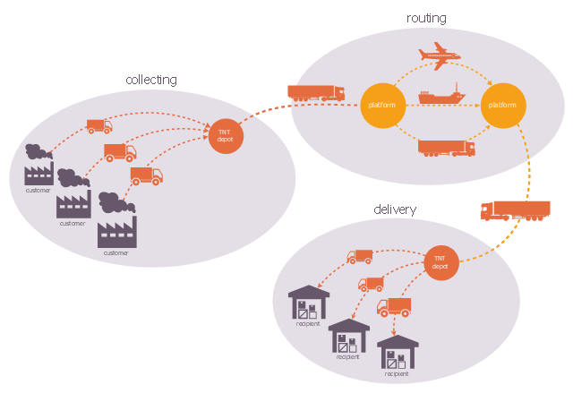
This logistic flow chart sample shows the schematization of the TNT Express integrator characteristics. Clean-up operations, transportation and delivery managed in its own right.
It was designed on the base of the Wikimedia Commons file: TNT Express, un intégrateur mondial. Schéma d'activité.jpg. [commons.wikimedia.org/ wiki/ File:TNT_ Express,_ un_ int%C3%A9grateur_ mondial._ Sch%C3%A9ma_ d%27activit%C3%A9.jpg]
This file is licensed under the Creative Commons Attribution-Share Alike 3.0 Unported license. [creativecommons.org/ licenses/ by-sa/ 3.0/ deed.en]
"TNT Express is an international courier delivery services company with headquarters in Hoofddorp, Netherlands. The firm has fully owned operations in 61 countries and delivers documents, parcels and pieces of freight to over 200 countries." [TNT Express
From Wikipedia]
The logistic flowchart example "Integrator features" was created using ConceptDraw PRO diagramming and vector drawing software extended with the Logistics Flow Charts solution from the Business Processes area of ConceptDraw Solution Park.
Logistic flowchart
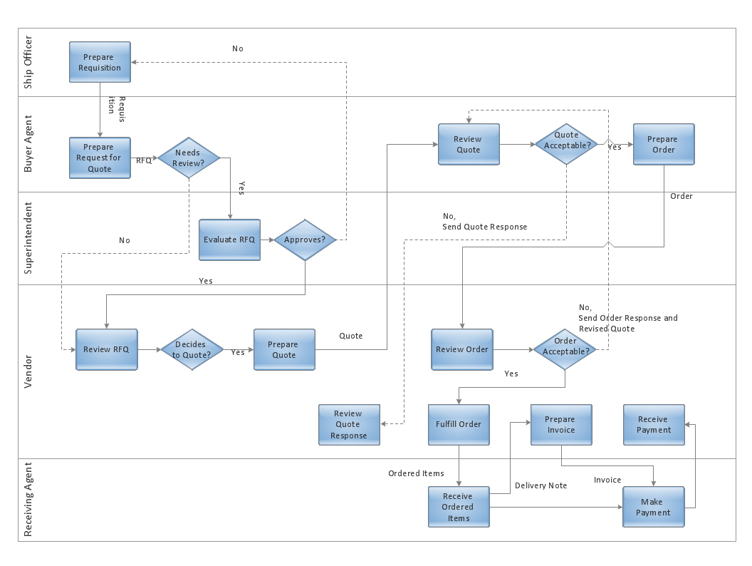
Business Process Flowchart
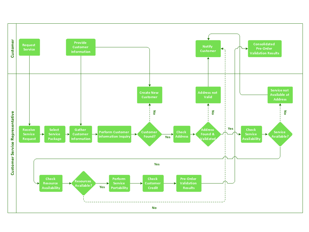
The flowcharts are divided into rows/columns of functional units. Blocks of various shapes represent the process steps, and are placed in rows/columns of the responsible functional units.
Structured Systems Analysis and Design Method (SSADM) with ConceptDraw DIAGRAM

ConceptDraw Arrows10 Technology

Process Flow Diagram Symbols
- Characteristics Of Flowchart
- Characteristics Of Flowchart In Computer
- Characteristics Of Good Flowchart
- Www Characteristics Of Flowchart Com
- Characteristics Of Algorithm And Flowchart
- Features Of Flowcharts And Importance In Algorithm Design
- ConceptDraw Arrows10 Technology | Flowcharts For Characteristics ...
- Basic Flowchart Symbols and Meaning | Characteristics Of Flow Chars
- Six Characteristics Of Flow Charts
- Characterstic Of Flowchart
- ERD | Entity Relationship Diagrams, ERD Software for Mac and Win
- Flowchart | Basic Flowchart Symbols and Meaning
- Flowchart | Flowchart Design - Symbols, Shapes, Stencils and Icons
- Flowchart | Flow Chart Symbols
- Electrical | Electrical Drawing - Wiring and Circuits Schematics
- Flowchart | Common Flowchart Symbols
- Flowchart | Common Flowchart Symbols