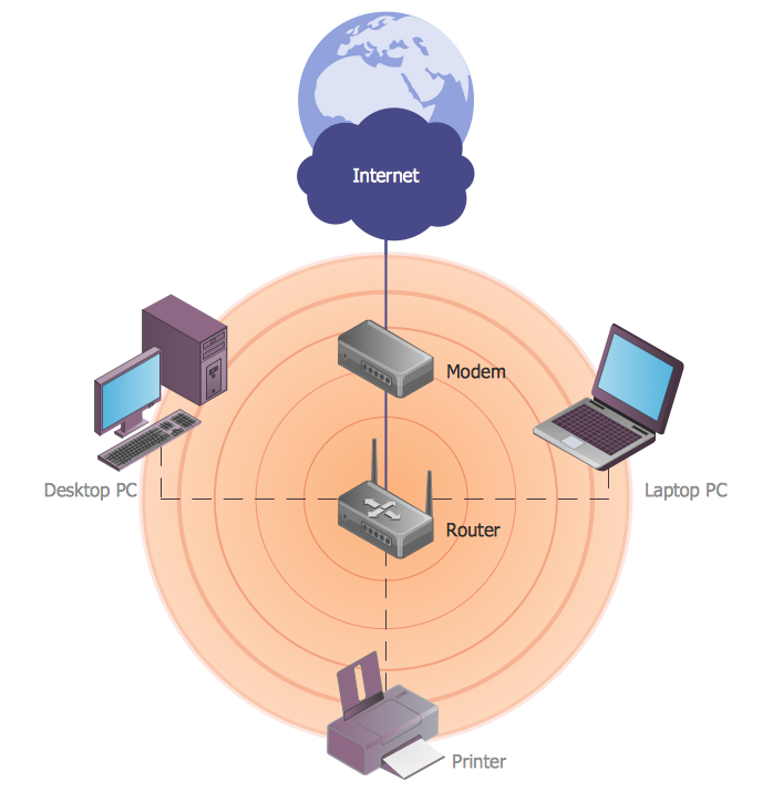
Star Network Topology

Use it to draw the physical and logical network topology diagrams for wired and wireless computer communication networks.

Bus Network Topology

Use it to draw the physical and logical network topology diagrams for wired and wireless computer communication networks.
Create your bus network topology diagrams using the ConceptDraw DIAGRAM.
Hybrid Network Topology

This is example of the Hybrid network topology.
Network topology is the topological structure of the computer network. There are many types of the network topologies: bus, star, ring, mesh topology, but the most popular is the hybrid topology.
Personal area (PAN) networks. Computer and Network Examples
 networks")
This example was created in ConceptDraw DIAGRAM using the Computer and Networks Area of ConceptDraw Solution Park and shows the Personal area network.

Wireless Network Topology

Wireless network topology shows how the computers connect each other when there is no physical connection. The computers communicate each using the wireless devices.
WLAN
Ring Network Topology

Overlay networks. Computer and Network Examples
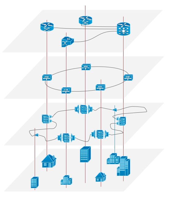
Overlay networks are widely used in telecommunication. They also allow to improve Internet routing.
Using the solutions of the Computer and Networks Area for ConceptDraw DIAGRAM with wide set of ready-to-use predesigned vector stencils and examples you can design anyone overlay networks quick and easy.
Cisco Network Templates

ConceptDraw has Cisco network diagram templates:
Wireless Mesh Network, Network Organization Chart, Roaming Wireless Local Area Network, Cisco ISG Topology Diagram, Cisco Express Forwarding Sample that facilitates drawing at the initial stage.
However for customizing Cisco network diagrams you can use 13 Libraries like this: Cisco Basic, Cisco Buildings, Cisco IBM, Cisco LAN, Cisco WAN, Cisco Media, Cisco Optical, Cisco People, Cisco Routers, Cisco Security, Cisco Switches&Hub, Cisco Telepresences, etc.
This take great advantage to you for designing Cisco network diagram templates.
ERD Symbols and Meanings

The Chen's ERD notation is still used and is considered to present a more detailed way of representing entities and relationships.
To create an ERD, software engineers mainly turn to dedicated drawing software, which contain the full notation resources for their specific database design - ERD symbols and meanings. CS Odessa has released an all-inclusive Entity-Relationship Diagram (ERD) solution for their powerful drawing program, ConceptDraw DIAGRAM.

- Extended Star Topology Definition
- Star Network Topology | 10Base-T star topology - Network diagram ...
- Star Network Topology | 10Base-T star topology - Network diagram ...
- Difference Between Star Topology And Extended Star Topology
- Hierarchical Or Extended Star Topology
- Extended Bus Topology
- Extended Star Topology Definition And Diagram
- Definition Extended Star Topology
- Advantages Of Using Logical Bus Extended Star Topology
- Graph Topology Advantages And Disadvantages
- Star Network Topology | Hybrid Network Topology | Fully Connected ...
- Star Network Topology | Hierarchical Network Topology | Network ...
- Components Required By Extended Star Topology
- Star Topology Examples Real Life
- Fully Connected Network Topology Diagram | Star Network ...
- Extended Star And Distributed Star Network Topology
- Star Network Topology | Bus Network Topology | Active Directory ...
- Star Network Topology | Bus Network Topology | Network ...
- Fully Connected Network Topology Diagram | Bus Network ...
- Extended Star Network Topology
- ERD | Entity Relationship Diagrams, ERD Software for Mac and Win
- Flowchart | Basic Flowchart Symbols and Meaning
- Flowchart | Flowchart Design - Symbols, Shapes, Stencils and Icons
- Flowchart | Flow Chart Symbols
- Electrical | Electrical Drawing - Wiring and Circuits Schematics
- Flowchart | Common Flowchart Symbols
- Flowchart | Common Flowchart Symbols