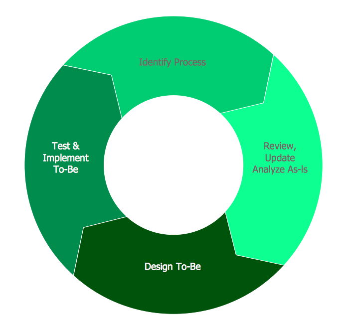
Scrum process work items and workflow
Scrum is a popular iterative and incremental agile framework for managing product and software development. For planning a project, tracking the defects, bugs, work and blocking issues when developing software, viewing and reporting a progress, the teams working with Scrum methodology use the product backlog items (PBIs), bug work item types (WITs), reports and dashboards. When defining a product backlog item, you can focus on the value which will be received by your customers without description how this will be achieved. Working in sprints, the teams can define tasks which automatically link to PBIs and bugs.
ConceptDraw DIAGRAM diagramming and vector drawing software extended with SCRUM Workflow solution from the Project Management area of ConceptDraw Solution Park offers collection of samples, variety of predesigned objects, clipart and graphic elements, a set of Scrum process work items and workflow which are developed for agile teams working using Scrum.
SCRUM Workflow Solution was specially designed to give you the opportunity to create Scrum diagrams and charts, visualize scrum processes and scrum workflow without efforts. Simply create new document and drag the needed objects from the libraries of SCRUM Workflow Solution to make your own professional looking and successful diagram or infographic.


8 libraries of the SCRUM Workflow Solution contain 276 objects, all they are vector and ready-to-use.
Pay special attention for the Scrum Charts library which offers 4 live objects:
- Release burndown chart - lets conviently track the progress on a Scrum project.
- Release velocity chart - helps to determine how many points worth of work can be completed per sprint for a given team.
- Sprint burndown chart - is used to track the product development effort remaining in a sprint.
- Team velocity chart - depicts the effort for a specific team against multiple sprints and multiple releases to compare team capacity against performance.
How to Create a Burndown Chart
Using the predesigned Scrum charts objects you can create your own chart in minutes - drag desired object from the library to your document, simply enter the values and they will be reflected instantly on the chart.
- Start a new document.
- Set a page orientation via File menu - Page Setup.

- From a Scrum charts library take a Sprint burndown chart object

- Enlarge the graph using sharp handle.
- Rename table columns headings.
- Related names on the graph will change automatically.

- Use object action menu.

- Set the needed quantity of points for the graph.
- For this case it is equal to the quantity of days from March 3rd to April 7th.

- For handful usage, move the table to a free space on the page.
- To do so, use a yellow control dot.

- Fill a table with data.
- To select a cell, click a few times on it.

- Use object action menu.

- Set the increment for Y axis.

- Use object action menu.

- Set the maximum value for Y axis.
- That value can't be less than a maximum number indicated in the table.

- Select a cell Real, select a Color menu.

- Set a color for the header cell.
- The color of the line graph and legend data will update automatically, as these parameters are connected.

- Use object action menu.
- Hide the table with data, you don't need it anymore.

- Stretch the graph adjusting it to the page size.

- Move the legend under the graph using a yellow control dot.

- Use layers inspector.
- Rename the second layer and set it as active.
- Lock the previous layer for editing.

- Use a rectangle from Drawing Shapes library.

- Stretch it out to the page size.

- Change the color.

- Open Fill color menu of Fill inspector.

- Uncheck the stroke for perimeter rectangle.

- Send it to Back using context menu.

- Open Layers inspector.
- Set the first layer as active.
- Lock the background layer for editing.

- If transparent graph lines dissapeared on the background, use a rectangle again.

- Set the needed size, select the graph by clicking on its components.
- Send the graph to Front.

- Select the graph object.
- Open line inspector.
- Set the line pattern to a solid one.

- Your document is ready!

- Save it and export to another format if needed.


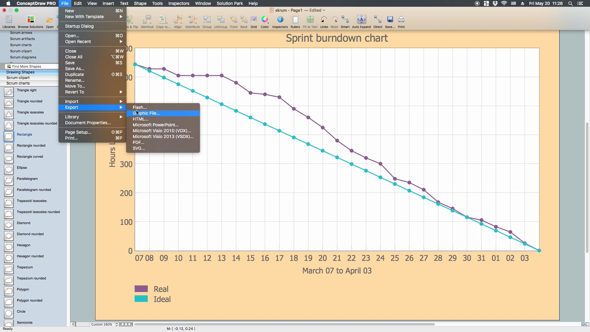
The possibility of exporting to variety of popular graphical formats (PNG, JPEG, JPG, GIF, TIF, TIFF, BMP, DIB, EMF, SVG) and file formats, such as Microsoft PowerPoint (PPT), Adobe Acrobat (PDF), Microsoft Visio (VDX, VSDX), Adobe Flash (SWF), Encapsulated PostScript (EPS), HTML, opens wide opportunities for you.
Video. How to Create a Burndown Chart (1min 08sec)
Use the tools of the SCRUM Workflow Solution for ConceptDraw DIAGRAM to create your own professional looking Scrum diagrams, represent scrum process work items and workflow fast, easy and effective.