Booch OOD Diagram

ER Diagram for Cloud Computing

Management Tools — Total Quality Management
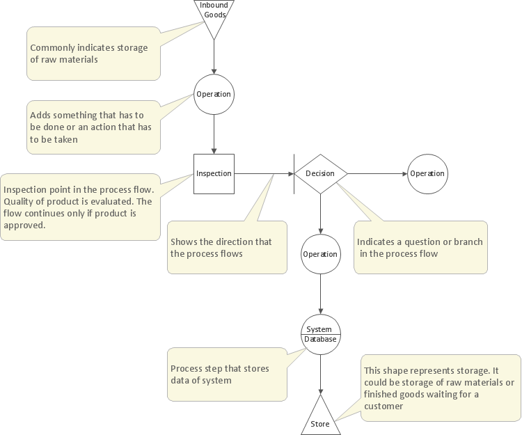
Example of DFD for Online Store (Data Flow Diagram)


DFD Flowchart Symbols

Jacobson Use Cases Diagram

CORRECTIVE ACTIONS PLANNING. Risk Diagram (PDPC)

 Enterprise Architecture Diagrams
Enterprise Architecture Diagrams solution extends ConceptDraw DIAGRAM software with templates, samples and library of vector stencils for drawing the diagrams of enterprise architecture models.
UML Deployment Diagram. Design Elements

How to create a UML Diagram

Bubble Chart
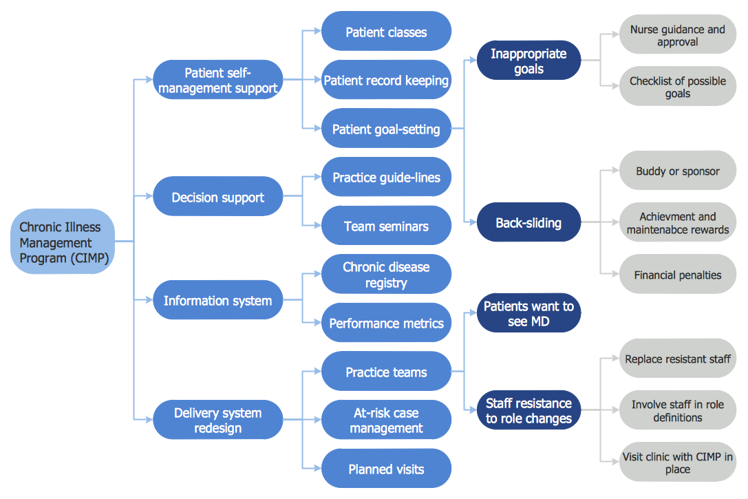
 Seven Management and Planning Tools
Seven Management and Planning Tools solution extends ConceptDraw DIAGRAM and ConceptDraw MINDMAP with features, templates, samples and libraries of vector stencils for drawing management mind maps and diagrams.
UML Diagram of Parking

UML Diagram for Mac

- 1 Level Dfd And Erd Of Medical Management System Project
- Er Diagram For Healthcare Management System
- Er Diagram For Medical Store Management System
- Er Diagram Of Medical Store Step By Step Showing System
- Medical Management System Erd Dfd
- Uml Diagram For Drug Management System
- E R Diagram For Medical Care Management
- Er Model For Medical Management System
- ER Diagram For Medical Management
- Database Management System Er Diagram
- Sequence Diagram For Electronic Shop Management System Project
- Erd For Medical Store Management System
- Data Flow Diagram Of Medical Store Management System
- Er Diagram For Pharmacy Management System
- Erd Dfd Of Medical Shop Management System
- Medical Management Er Diagram
- Medical Store Management System Erd
- Er Diagram Of Medicine Store Management System
- Er Digram For Medical Management
- ER Diagram Of Medical Store Database Management System