Metropolitan area networks (MAN). Computer and Network Examples
. Computer and Network Examples")

Using Fishbone Diagrams for Problem Solving
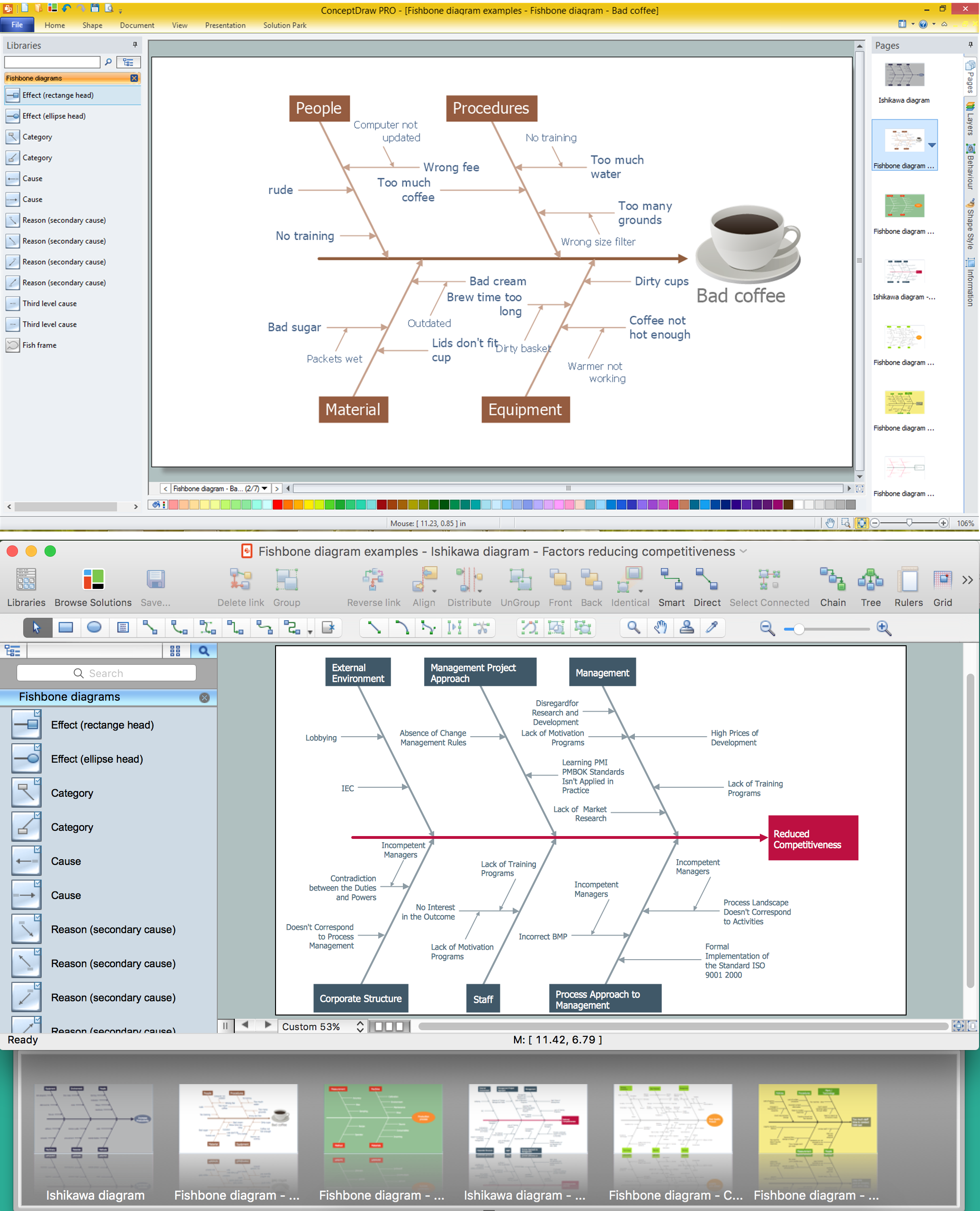
Fishbone Diagram Problem Solving

Network Configuration

OSPF Network. Computer and Network Examples

Network Diagram Software Logical Network Diagram

 Wireless Networks
The Wireless Networks Solution extends ConceptDraw DIAGRAM software with professional diagramming tools, set of wireless network diagram templates and samples, comprehensive library of wireless communications and WLAN objects to help network engineers and designers efficiently design and create Wireless network diagrams that illustrate wireless networks of any speed and complexity, and help to identify all required equipment for construction and updating wireless networks, and calculating their costs.
Basic Network Diagram

IDEF9 Standard

Block Diagram

ConceptDraw DIAGRAM - Organizational chart software

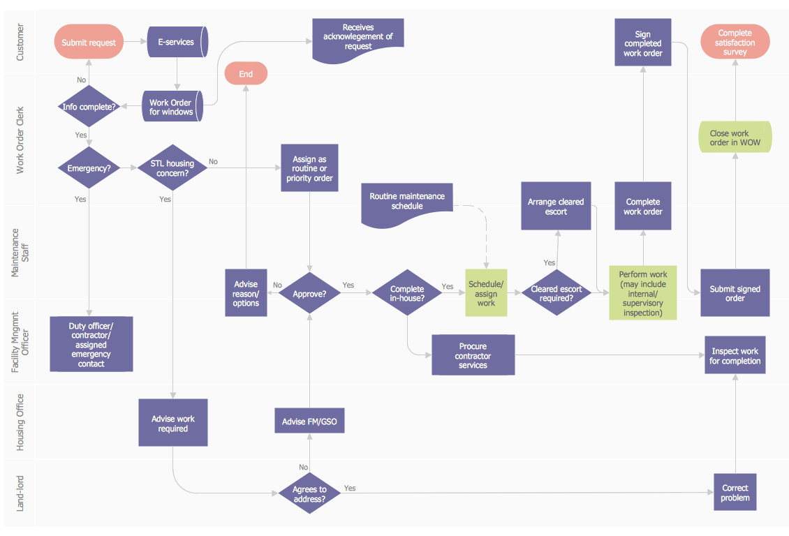
 Business Process Mapping
The Business Process Mapping solution for ConceptDraw DIAGRAM is for users involved in process mapping and creating SIPOC diagrams.
Work Order Process Flowchart. Business Process Mapping Examples
The vector stencils library "Bearings" contains 59 symbols of ball bearings, roller bearings, shafts, springs, gears, hooks, spindles, and keys.
Use it to design engineering drawings of machine tools and mechanical devices.
"A bearing is a machine element that constrains relative motion and reduce friction between moving parts to only the desired motion. The design of the bearing may, for example, provide for free linear movement of the moving part or for free rotation around a fixed axis; or, it may prevent a motion by controlling the vectors of normal forces that bear on the moving parts. Many bearings also facilitate the desired motion as much as possible, such as by minimizing friction. Bearings are classified broadly according to the type of operation, the motions allowed, or to the directions of the loads (forces) applied to the parts." [Bearing (mechanical). Wikipedia]
The shapes example "Design elements - Bearings" was created using the ConceptDraw PRO diagramming and vector drawing software extended with the Mechanical Engineering solution from the Engineering area of ConceptDraw Solution Park.
Bearing symbols

- The Diagram Of Head Pan
- Business Process Mapping | Head Pan Diagram And Uses
- What Is Headpan Used For
- What Is Headpan Used For In Site
- Head Pan Uses
- Metropolitan area networks (MAN). Computer and Network Examples
- Uses And Maintanance Of Head Pan
- Use Ofhead Pan And It Diagram
- What Are The Uses Of Headpan
- What Are The Uses Of A Head Pan
- Use Of Head Pan
- With Aid Of A Diagram Draw Head Pan
- Headpan Description
- Metropolitan area networks (MAN). Computer and Network Examples
- Basic Network Diagram | Wireless Networks | Draw A Head Pan
- Process Flowchart | Network Diagram Software LAN Network ...
- Diagram Of A Well Labeled Head Pan
- Personal area ( PAN ) networks. Computer and Network Examples ...
- Lighting and switch layout | How To use House Electrical Plan ...