Network Security Devices

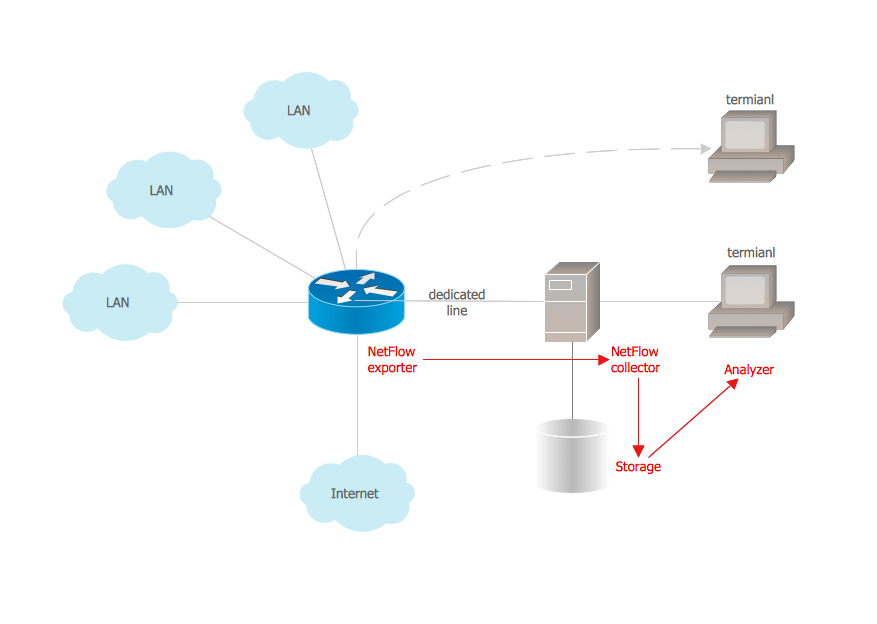
Netflow architecture. Computer and Network Examples

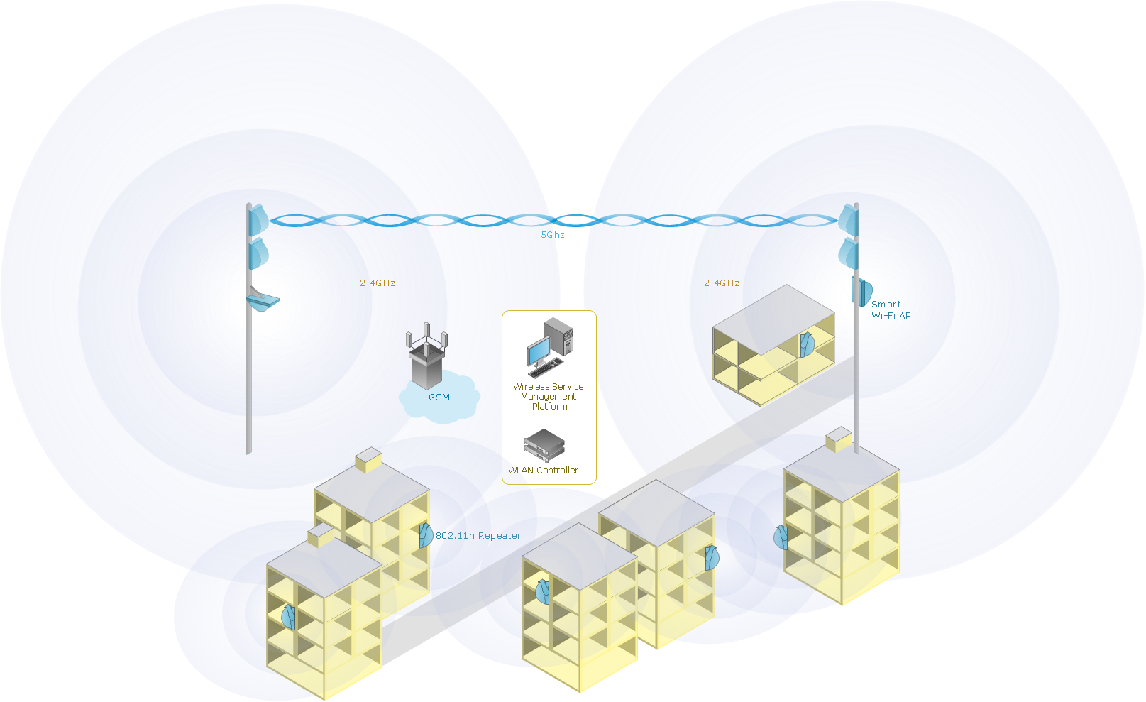
Wireless Network Setup
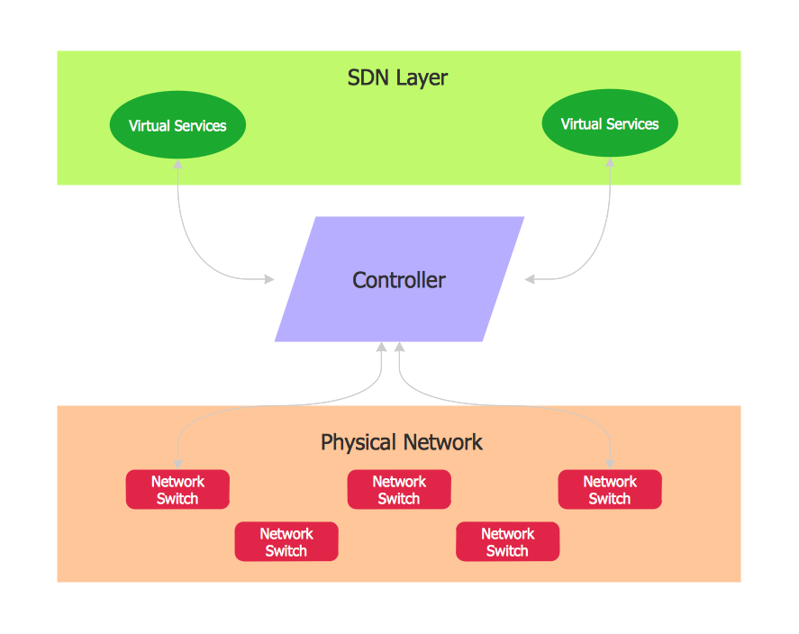
Software Defined Networking System Overview
Ring Network Topology

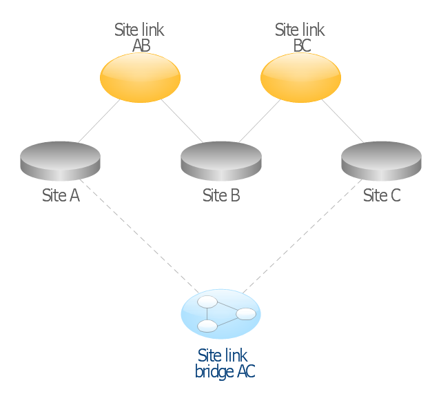
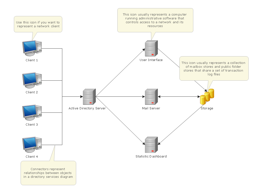
This AD diagram example was redesigned from the picture "Site links" from the book "Active Directory for Dummies".
"Site links represent the Active Directory replication paths between sites.
These paths are manually defined so that the designer has control over which network links the replication traffic occurs on. These site links also control how clients are directed to domain controllers when there’s no DC in the client’s local site. Each site link has the following attributes:
(1) Connected sites: A site link is defined by the sites to which it connects. A site link can connect two or more sites together.
(2) Network transport: Site links support replication communication over IP-based RPCs or with the Simple Mail Transport Protocol (SMTP). You normally want to use RPC whenever possible, but you can use SMTP when the sites you’re linking don’t support RPC.
(3) Cost: Each site link has a cost associated with it. Costs are used to assign preferences to links that determine which link should be followed when multiple link paths are available between sites. The cost represents what it “costs” to use this site link relative to the other site links and affects replication traffic as well as how users are assigned a domain controller. Links with lower cost values have preference over links with higher cost values. Cost values range from 1–32,767; the default being 100.
(4) Frequency: The frequency value defines how often a replication occurs
when using this site link (the replication latency). You can configure the time between replications from a minimum of 15 minutes to a maximum of 10,080 minutes (one week). The default frequency is 180 minutes.
(5) Schedule: The schedule dictates when this link is active and available for replication between the sites. The schedule can also control which days of the week the link is available. Normally, the schedule is set so that the link is available 24 hours a day, but you can set up different schedules on a per-day-of-the-week basis.
By creating a site link, you enable two or more sites to be connected and to share the same site link attributes (transport, cost, frequency, and schedule). By default, site links create transitive connectivity between sites.
If you create a site link between sites A and B and another site link between
sites B and C, an automatic connection (known as a site link bridge) is created between sites A and C..." [Steve Clines and Marcia Loughry, Active Directory® For Dummies®, 2nd Edition. 2008]
The Active Directory diagram example "Site links" was created using the ConceptDraw PRO diagramming and vector drawing software extended with the Active Directory Diagrams solution from the Computer and Networks area of ConceptDraw Solution Park.
Active Directory network diagram
Cisco Routers. Cisco icons, shapes, stencils and symbols

Network Visualization with ConceptDraw DIAGRAM
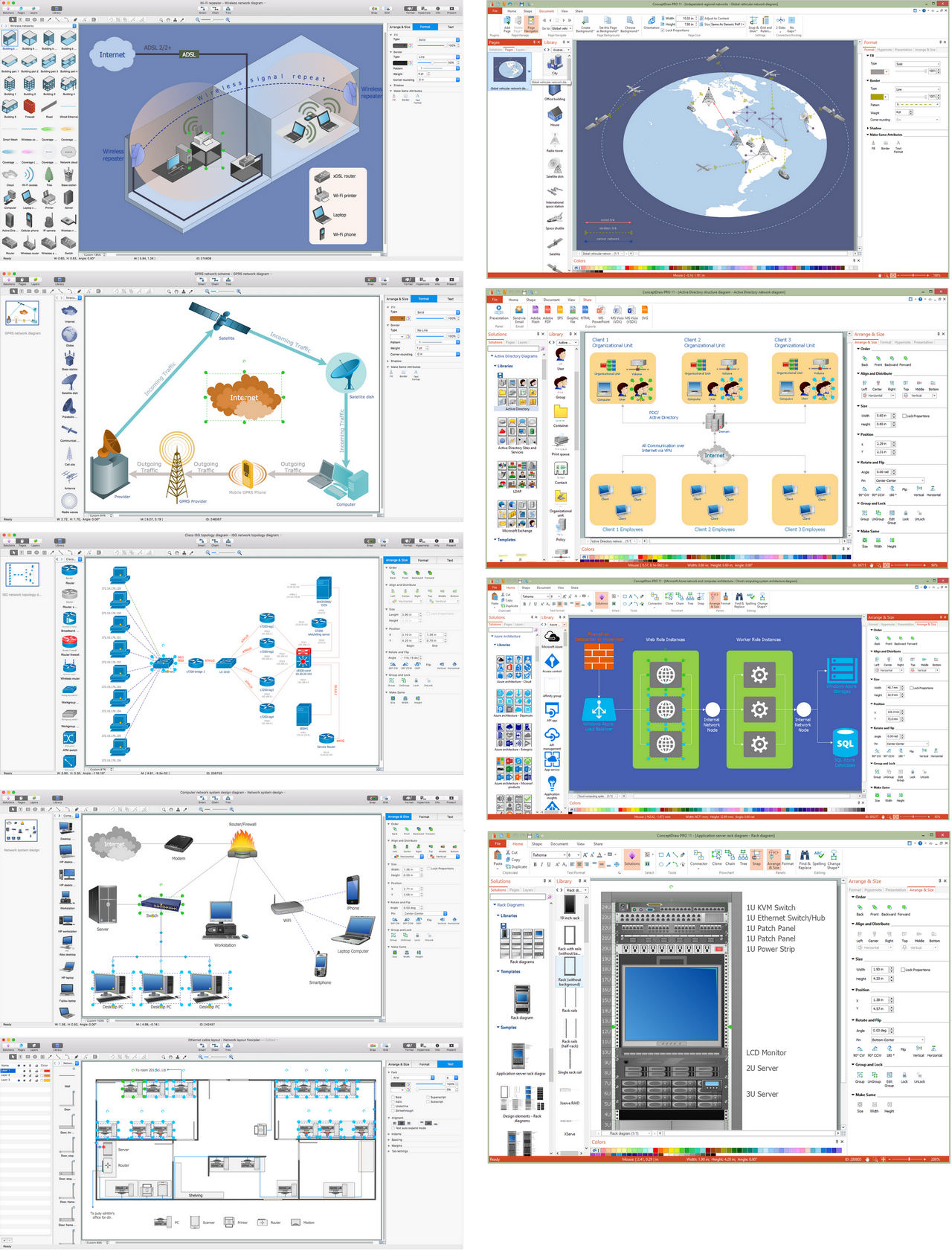
 Wireless Networks
The Wireless Networks Solution extends ConceptDraw DIAGRAM software with professional diagramming tools, set of wireless network diagram templates and samples, comprehensive library of wireless communications and WLAN objects to help network engineers and designers efficiently design and create Wireless network diagrams that illustrate wireless networks of any speed and complexity, and help to identify all required equipment for construction and updating wireless networks, and calculating their costs.
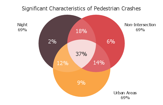
This Venn diagram sample shows the significant characteristics of pedestrian crashes. It was designed on the base of the Venn diagram in the "Pedestrian Safety Strategic Plan: Recommendations for Research and Product Development" from the website of the Federal Highway Administration of the U.S. Department of Transportation. [safety.fhwa.dot.gov/ ped_ bike/ pssp/ fhwasa10035/ ]
"Road traffic safety refers to the methods and measures used to prevent road users from being killed or seriously injured. Typical road users include pedestrians, cyclists, motorists, vehicle passengers, and passengers of on-road public transport (mainly buses and trams).
Best-practices in modern road safety strategies focus on preventing serious injury and death from vehicle crashes despite human fallibility." [Road traffic safety. Wikipedia]
The Venn diagram example "Significant characteristics of pedestrian crashes" was created using the ConceptDraw PRO diagramming and vector drawing software extended with the Venn Diagrams solution from the area "What is a Diagram" of ConceptDraw Solution Park.
Venn diagram
Active Directory Domain Services
This computer security diagram example was designed on the base of the Wikimedia Commons file: Firewall.png.
[commons.wikimedia.org/ wiki/ File:Firewall.png]
This file is licensed under the Creative Commons Attribution-Share Alike 3.0 Unported license. [creativecommons.org/ licenses/ by-sa/ 3.0/ deed.en]
"In computing, a firewall is a network security system that monitors and controls the incoming and outgoing network traffic based on predetermined security rules. A firewall typically establishes a barrier between a trusted, secure internal network and another outside network, such as the Internet, that is assumed to not be secure or trusted. Firewalls are often categorized as either network firewalls or host-based firewalls. Network firewalls are a software appliance running on general purpose hardware or hardware-based firewall computer appliances that filter traffic between two or more networks. Host-based firewalls provide a layer of software on one host that controls network traffic in and out of that single machine. Firewall appliances may also offer other functionality to the internal network they protect such as acting as a DHCP or VPN server for that network." [Firewall (computing). Wikipedia]
The cybersecurity diagram example "Firewall between LAN and WAN" was created using the ConceprDraw PRO software extended with the Network Security Diagrams solution from the Computer and Neworks area of ConceptDraw Solution Park.
Computer security diagram

Design Element: Computer and Network for Network Diagrams
.png)
Road Transport - Design Elements
Star Network Topology


- Network Traffic System Class Diagram
- Aerospace and Transport | Telecommunication Network Diagrams ...
- Traffic Management System Uml Diagrams
- Diagrams Of Road Traffic Signs
- Traffic Complaex Diagram
- Diagram Of City Traffic
- Traffic In City Diagram For School Project
- Physics Diagrams | Design elements - Road signs | | Traffic Signals ...
- Traffic Signal Diagrams
- City Traffic Signal Diagram
- Network Glossary Definition | Telecommunication Network Diagrams ...
- Traffic Division Network Diagram For Police Station
- Diagrams Of All Traffic Signs
- Draw The Diagram Of Traffic Sign
- Diagrams For Pictures On City Traffic
- Vehicular Networking | How to Create a Vehicular Network Diagram ...
- Traffic Road Diagrams
- Diagrams Of Traffic Signs
- Diagram And Explanation Of Traffic Signs
- Diagram Of Traffic Road Sign