Cisco Network Topology. Cisco icons, shapes, stencils and symbols

Local area network (LAN). Computer and Network Examples
 diagram")

The vector stencils library "Network layout floorplan" contain 34 symbol icons for drawing computer network floor plans and communication equipment and cabling layouts.
"Networking hardware may also be known as network equipment or computer networking devices. Units which are the last receiver or generate data are called hosts or data terminal equipment.
All these terms refer to devices facilitating the use of a computer network. Specifically, they mediate data in a computer network. ...
Typically, networking hardware includes gateways, routers, network bridges, switches, hubs, and repeaters. But it also includes hybrid network devices such as multilayer switches, protocol converters, bridge routers, proxy servers, firewalls, network address translators, multiplexers, network interface controllers, wireless network interface controllers, modems, ISDN terminal adapters, line drivers, wireless access points, networking cables and other related hardware.
The most common kind of networking hardware today is a copper-based Ethernet adapter because of its standard inclusion on most modern computer systems. Wireless networking has, however, become increasingly popular, especially for portable and handheld devices.
Other hardware prevalent in computer networking includes data center equipment (such as file servers, database servers and storage areas), network services (such as DNS, DHCP, email, etc.) as well as devices which assure content delivery." [Networking hardware. Wikipedia]
The shapes example "Design elements - Network layout floorplan" was created using the ConceptDraw PRO diagramming and vector drawing software extended with the Network Layout Floor Plans solution from the Computer and Networks area of ConceptDraw Solution Park.
Network layout floor plan symbols

Cisco Routers. Cisco icons, shapes, stencils and symbols

Network Icon

Network Diagram Software. LAN Network Diagrams. Physical Office Network Diagrams

Wireless Networking for Mac
The vector stencils library "Local vehicular networking" contains 88 symbols for drawing the vehicular computer telecommunication network diagrams using the ConceptDraw PRO diagramming and vector drawing software.
"A vehicular ad hoc network (VANET) uses cars as mobile nodes in a MANET to create a mobile network.[1] A VANET turns every participating car into a wireless router or node, allowing cars approximately 100 to 300 metres of each other to connect and, in turn, create a network with a wide range. As cars fall out of the signal range and drop out of the network, other cars can join in, connecting vehicles to one another so that a mobile Internet is created. It is estimated that the first systems that will integrate this technology are police and fire vehicles to communicate with each other for safety purposes. ...
Vehicular ad hocal networks are expected to implement wireless technologies such as dedicated short-range communications (DSRC) which is a type of Wi-Fi. Other candidate wireless technologies are cellular, satellite, and WiMAX. Vehicular ad hoc networks can be viewed as component of the intelligent transportation systems (ITS).
As promoted in ITS, vehicles communicate with each other via inter-vehicle communication (IVC) as well as with roadside base stations via roadside-to-vehicle communication (RVC)." [Vehicular ad hoc network. Wikipedia]
The example "Design elements - Local vehicular networking" is included in the Vehicular Networking solution from the Computer and Networks area of ConceptDraw Solution Park.
Vehicular network diagram symbols
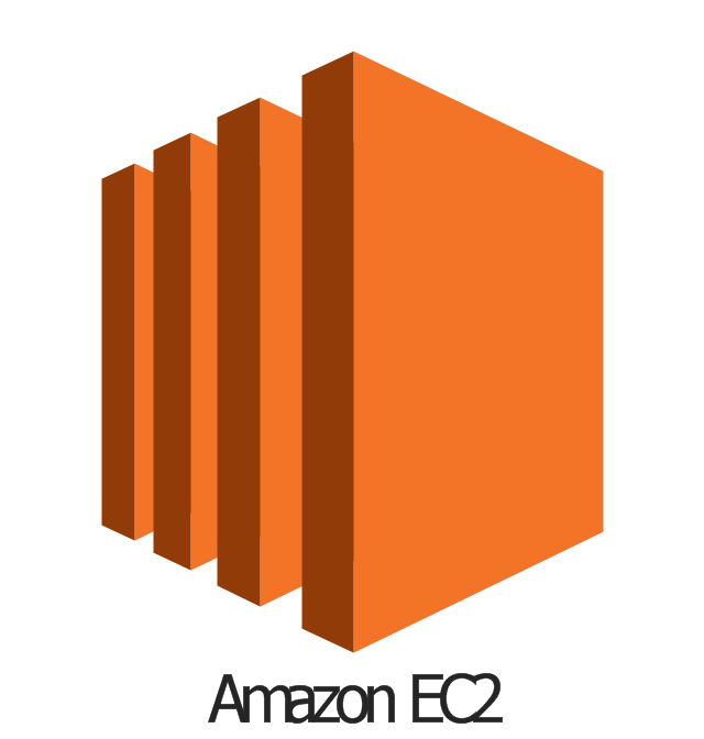
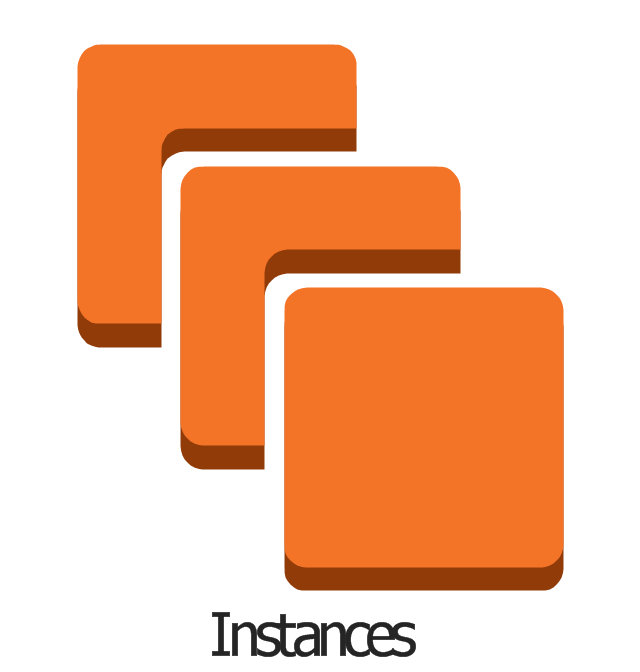
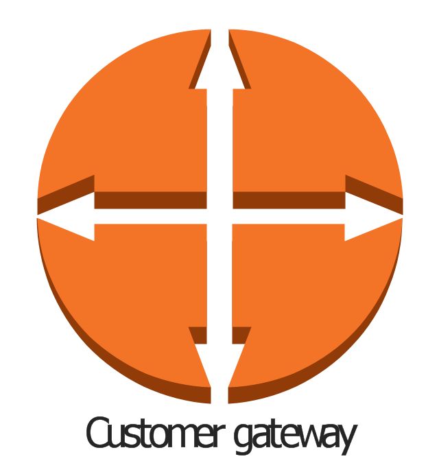
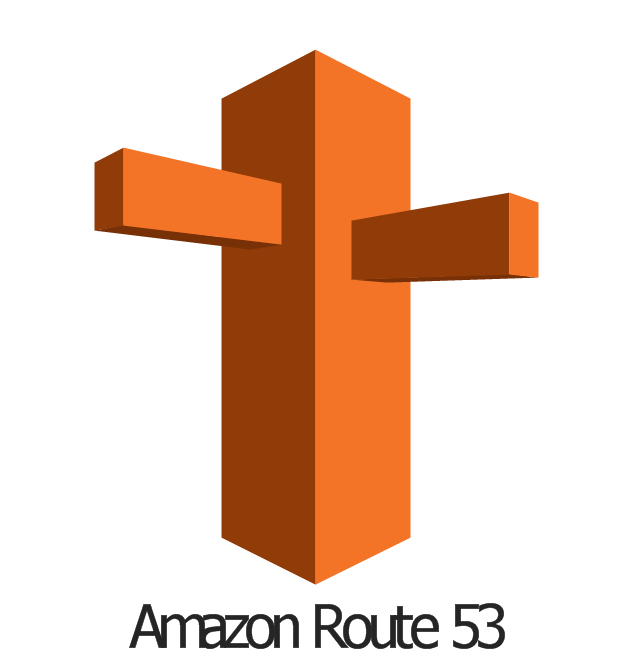
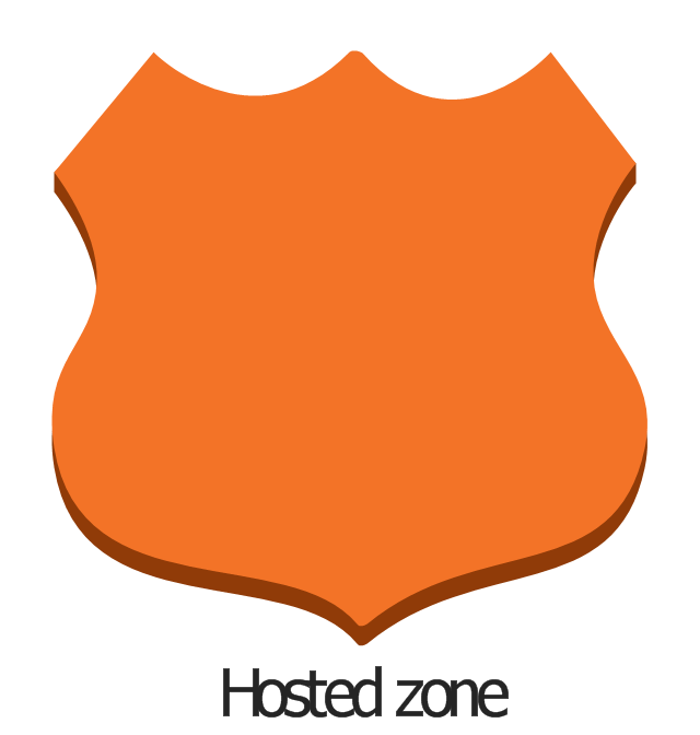
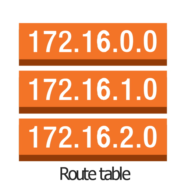
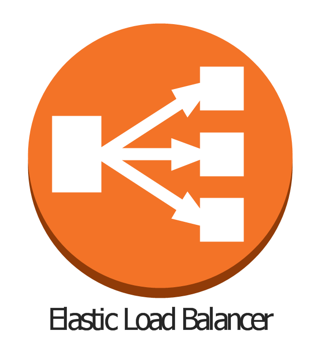
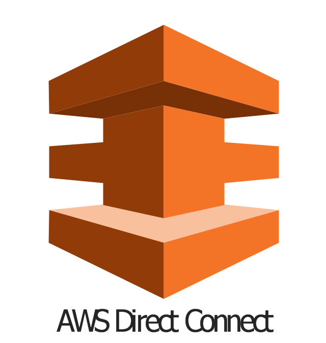
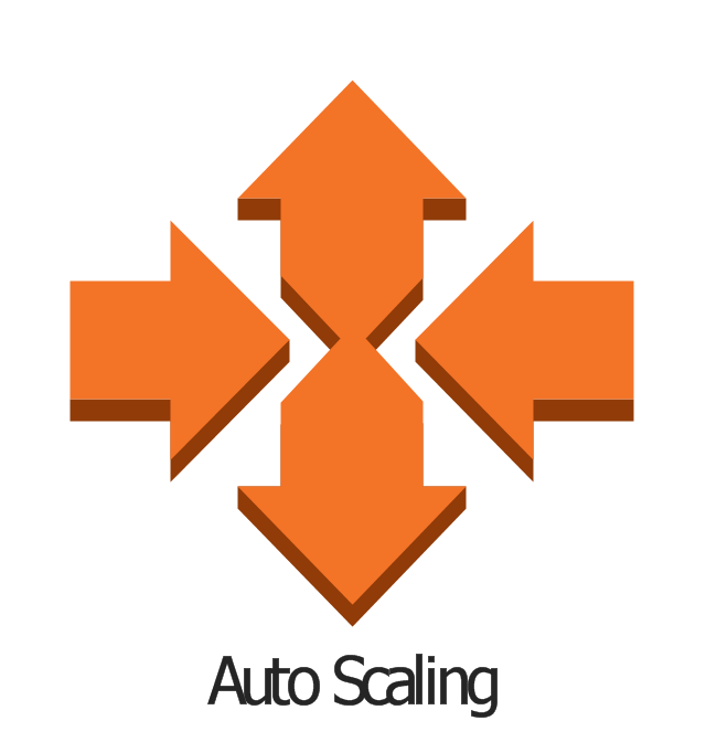
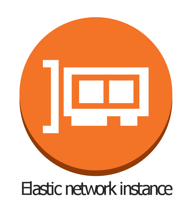
The vector stencils library "AWS Compute and Networking" contains 23 Amazon Web Services compute and networking icons: Amazon Elastic Compute Cloud symbols, Amazon Virtual Private Cloud symbols, Amazom Route 53 symbols, Elastic Load Balancing symbol, AWS Direct Connect symbol, Auto Scaling symbol, Elastic Network Instance symbol. Use it to draw AWS architecture diagrams of your cloud service. The symbols example "AWS Compute and Networking - Vector stencils library" was created using the ConceptDraw PRO diagramming and vector drawing software extended with the AWS Architecture Diagrams solution from the Computer and Networks area of ConceptDraw Solution Park.
Amazon EC2
Instance

Instances
AMI
DB on instance

Instance with CloudWatch

Elastic IP

Optimized instance
Amazon Lambda

Amazon VPC
Router
Internet gateway

Customer gateway
Virtual private gateway

VPN connection

VPC peering

Amazon Route 53
Hosted zone
Route table
Elastic Load Balancer
AWS Direct Connect
Auto Scaling
Elastic network instance
Cisco Switches and Hubs. Cisco icons, shapes, stencils and symbols

Using Remote Networking Diagrams

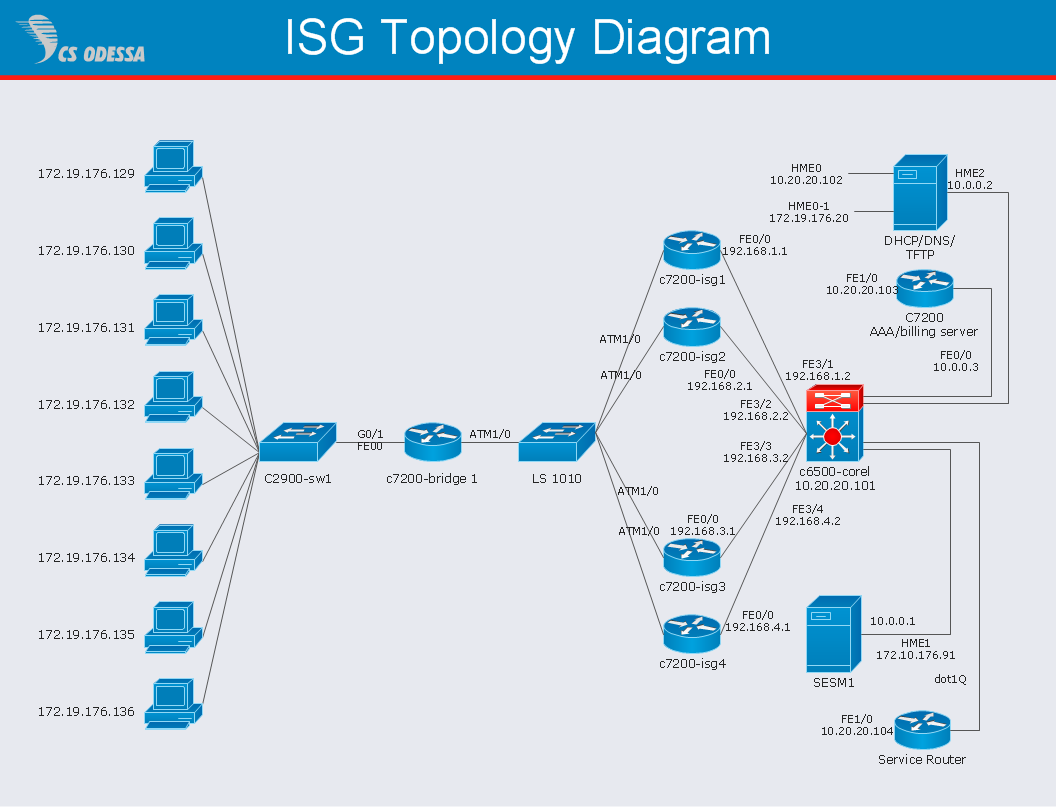
Network Diagram Software ISG Network Diagram
Mesh Network Topology Diagram

Network Configuration

UML Use Case Diagram Example. Social Networking Sites Project

- Cisco Network Topology. Cisco icons, shapes, stencils and symbols ...
- Cisco Routers. Cisco icons, shapes, stencils and symbols | Cisco ...
- Internet symbols - Vector stencils library | Internet symbols - Vector ...
- Cisco Switches and Hubs. Cisco icons, shapes, stencils and symbols
- Communication network diagram | Cisco Network Topology. Cisco ...
- Router Symbols In Networking
- Networking Symbol
- Vehicular Networking | Computer Network Diagrams | Basic ...
- Wireless router network diagram | Cisco Routers. Cisco icons ...
- Computer and Networks Area | Basic Flowchart Symbols and ...
- Process Flowchart | Electrical Symbols , Electrical Diagram Symbols ...
- Computer Networking Tools List | Basic Flowchart Symbols and ...
- Cisco Network Diagrams | Cisco Network Design. Cisco icons ...
- Network Printer | Wireless Networking | Cisco LAN. Cisco icons ...
- Cisco Network Design. Cisco icons, shapes, stencils, symbols and ...
- Cisco Network Diagrams | Cisco Network Topology. Cisco icons ...
- Telecommunication Network Diagrams | Design elements ...
- Basic Flowchart Symbols and Meaning | Fully Connected Network ...
- Star Network Topology | Tree Network Topology Diagram | Hotel ...
- Network Icon | Cisco Network Topology. Cisco icons, shapes ...