Flow Chart Symbols

Work Flow Chart

Basic Flowchart Symbols and Meaning


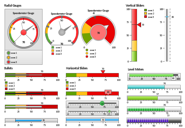
The vector stencils library "Meter indicators" contains 29 Live Objects: speedometer gauge, dial, bullet graph, slider and level meter visual indicators.
The Live Objects designed to display actual measures of performance metrics and KPIs from external data source files.
Some of them also display comparative measures, and colored zones of qualitative ranges with legend.
Use it to draw business performance dashboards using the ConceptDraw PRO diagramming and vector drawing software .
"Digital dashboards may be laid out to track the flows inherent in the business processes that they monitor. Graphically, users may see the high-level processes and then drill down into low level data. This level of detail is often buried deep within the corporate enterprise and otherwise unavailable to the senior executives. ...
Specialized dashboards may track all corporate functions. Examples include human resources, recruiting, sales, operations, security, information technology, project management, customer relationship management and many more departmental dashboards. ...
Like a car's dashboard (or control panel), a software dashboard provides decision makers with the input necessary to "drive" the business. Thus, a graphical user interface may be designed to display summaries, graphics (e.g., bar charts, pie charts, bullet graphs, "sparklines," etc.), and gauges (with colors similar to traffic lights) in a portal-like framework to highlight important information. ...
Digital dashboards allow managers to monitor the contribution of the various departments in their organization. To gauge exactly how well an organization is performing overall, digital dashboards allow you to capture and report specific data points from each department within the organization, thus providing a "snapshot" of performance." [Dashboard (management information systems). Wikipedia]
The example "Design elements - Meter indicators" is included in the Meter Dashboard solution from the area "What is a Dashboard" of ConceptDraw Solution Park.
Visual indicators
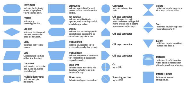
The vector stencils library "Flowchart" contains 26 symbols for drawing the flow charts using the ConceptDraw PRO diagramming and vector drawing software.
"Flowcharts are used in designing and documenting complex processes or programs. Like other types of diagrams, they help visualize what is going on and thereby help the viewer to understand a process, and perhaps also find flaws, bottlenecks, and other less-obvious features within it. There are many different types of flowcharts, and each type has its own repertoire of boxes and notational conventions. The two most common types of boxes in a flowchart are:
(1) a processing step, usually called activity, and denoted as a rectangular box;
(2) a decision, usually denoted as a diamond.
A flowchart is described as "cross-functional" when the page is divided into different swimlanes describing the control of different organizational units. A symbol appearing in a particular "lane" is within the control of that organizational unit. This technique allows the author to locate the responsibility for performing an action or making a decision correctly, showing the responsibility of each organizational unit for different parts of a single process. ...
Common alternate names include: flowchart, process flowchart, functional flowchart, process map, process chart, functional process chart, business process model, process model, process flow diagram, work flow diagram, business flow diagram. The terms "flowchart" and "flow chart" are used interchangeably." [Flowchart. Wikipedia]
The example "Design elements - Flowchart" is included in the Flowcharts solution from the area "What is a Diagram" of ConceptDraw Solution Park.
Flowchart notation
Cross-Functional Flowchart


Cross-Functional Flowcharts in ConceptDraw

UML Collaboration Diagram. Design Elements

Accounting Flowchart Purchasing Receiving Payable and Payment

DFD Library — Design elements

DFD Library System

Design Elements for UML Diagrams

Diagramming Software for Design UML Package Diagrams


HelpDesk
How to Protect a Document From Performing Unwanted Operations

Garrett IA Diagrams with ConceptDraw PRO

- Design elements - Comparison charts and indicators | Performance ...
- Performance Indicators | Enterprise dashboard | Design elements ...
- Design elements - Sales KPIs and metrics | Performance Indicators ...
- How to Create a Sales Dashboard Using ConceptDraw PRO ...
- Dashboard Design
- Balanced Scorecard Software | Design elements - Meter indicators ...
- Design elements - Meter indicators | Meter indicators 2 - Vector ...
- Enterprise dashboard | Design elements - Meter indicators | LLNL ...
- Performance Indicators | What is a KPI? | Constant improvement of ...
- How to Create Project Dashboard on Mac | Design elements - Meter ...
- Cafe performance metrics vs. air temperature - Visual dashboard ...
- Design elements - HR department | Human Resource Development ...
- Design elements - Meter indicators
- CORRECTIVE ACTIONS PLANNING. PERT Chart | PERT Chart ...
- Balanced Scorecard Software | Market Chart | Enterprise dashboard ...
- Enterprise dashboard | Design elements - Meter indicators | How to ...
- Enterprise dashboard | Design elements - Meter indicators ...
- Enterprise dashboard | KPI Dashboard | How to Connect a Live ...
- Gauges Chart Software
- Process Flowchart | Vertical Cross Functional Flowchart | Design ...