The vector stencil library "HVAC control equipment" contains 81 HVAC control equipment icons.
Use it for drawing HVAC system diagrams, heating, ventilation, air conditioning, refrigeration, automated building control, and environmental control design floor
plans and equipment layouts.
"HVAC (stands for Heating, Ventilation and Air Conditioning) is a control system that applies regulation to a heating and/ or air conditioning system. Usually a sensing device is used to compare the actual state (e.g., temperature) with a target state. Then the control system draws a conclusion what action has to be taken (e.g., start the blower).
More complex HVAC systems can interface to Building Automation System (BAS) to allow the building owners to have more control over the heating or cooling units. The building owner can monitor the system and respond to alarms generated by the system from local or remote locations." [HVAC control system. Wikipedia]
The vector stencils example "Design elements - HVAC control equipment" is included in HVAC Plans solution from the Building Plans area of ConceptDraw Solution
Park.
HVAC control equipment symbols

This HVAC plan sample shows the air handler layout on the floor plan.
"An air handler, or air handling unit (often abbreviated to AHU), is a device used to condition and circulate air as part of a heating, ventilating, and air-conditioning (HVAC) system. An air handler is usually a large metal box containing a blower, heating or cooling elements, filter racks or chambers, sound attenuators, and dampers. Air handlers usually connect to a ductwork ventilation system that distributes the conditioned air through the building and returns it to the AHU. Sometimes AHUs discharge (supply) and admit (return) air directly to and from the space served without ductwork.
Small air handlers, for local use, are called terminal units, and may only include an air filter, coil, and blower; these simple terminal units are called blower coils or fan coil units. A larger air handler that conditions 100% outside air, and no recirculated air, is known as a makeup air unit (MAU). An air handler designed for outdoor use, typically on roofs, is known as a packaged unit (PU) or rooftop unit (RTU)." [Air handler. Wikipedia]
The floor plan example "Air handler - HVAC plan" was created using the ConceptDraw DIAGRAM diagramming and vector drawing software extended with the HVAC Plans solution from the Building Plans area of ConceptDraw Solution Park.
Floor plan

Mac Diagramming Software
Network Diagramming Software for Design Network Layout Diagrams
_Win_Mac.png)

 Vehicular Networking
The Vehicular Networking solution extends the ConceptDraw DIAGRAM software functionality with specialized tools, wide variety of pre-made vector objects, collection of samples and templates in order to help network engineers design vehicular network diagrams for effective network engineering activity, visualize vehicular networks, develop smart transportation systems, design various types of vehicle network management diagrams, regional network diagrams, vehicular communication system diagrams, vehicular ad-hoc networks, vehicular delay-tolerant networks, and other network engineering schemes.
Functional Block Diagram

 Remote Presentation for Skype
This solution extends ConceptDraw MINDMAP software with the ability to collaborate via Skype.
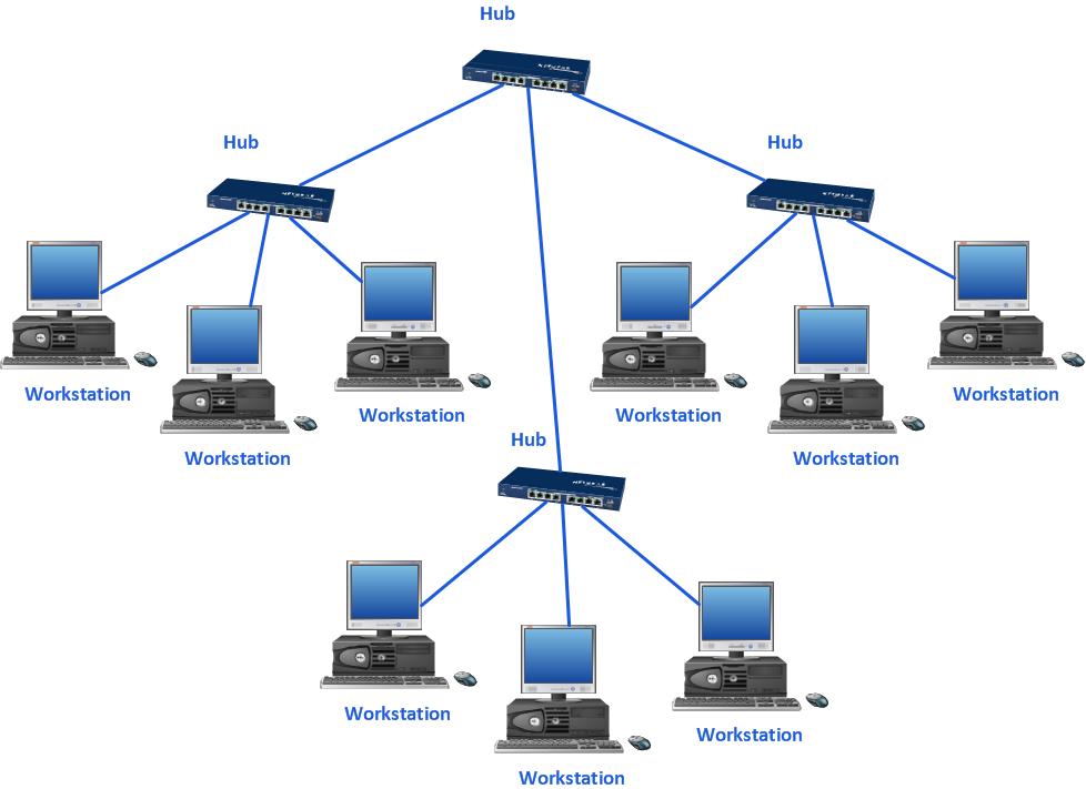
Home area networks (HAN). Computer and Network Examples

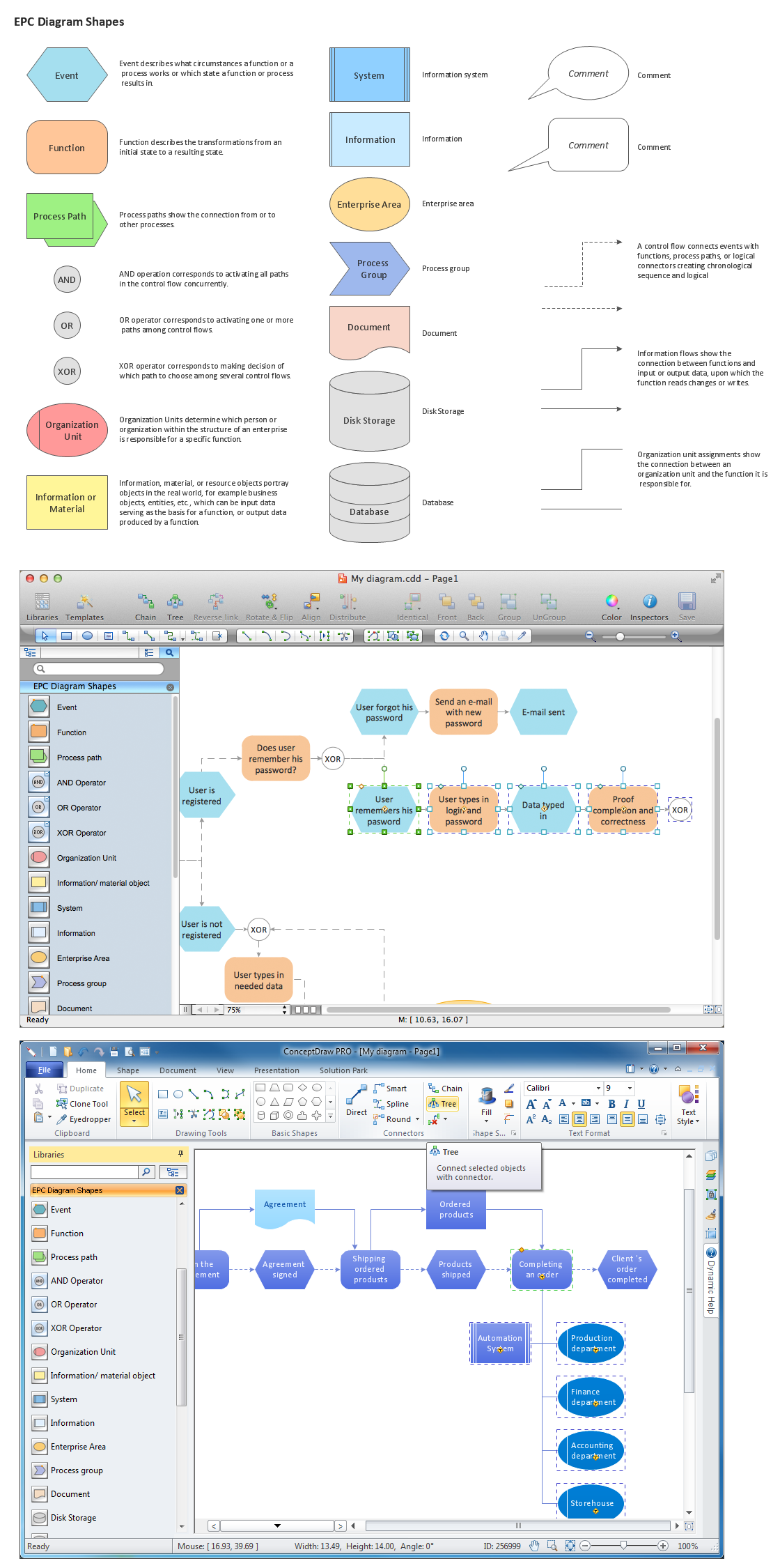
The Building Blocks Used in EPC Diagrams
 Cisco Network Diagrams
Cisco Network Diagrams solution extends ConceptDraw DIAGRAM with the best characteristics of network diagramming software. Included samples, templates and libraries of built-in standardized vector Cisco network icons and Cisco symbols of computers, network devices, network appliances and other Cisco network equipment will help network engineers, network designers, network and system administrators, as well as other IT professionals and corporate IT departments to diagram efficiently the network infrastructure, to visualize computer networks topologies, to design Cisco computer networks, and to create professional-looking Cisco Computer network diagrams, Cisco network designs and schematics, Network maps, and Network topology diagrams in minutes.
 Metro Map
Metro Map solution extends ConceptDraw DIAGRAM software with templates, samples and library of vector stencils for drawing the metro maps, route maps, bus and other transport schemes, or design tube-style infographics.
Emergency Plan


- Instruments - Vector stencils library | HVAC control equipment ...
- Design elements - HVAC control equipment | Instruments - Vector ...
- HVAC Plans | Block diagram - Automotive HVAC system | Design ...
- Design elements - HVAC controls | Instruments - Vector stencils ...
- Hvac Symbols Flow Meter
- Design elements - HVAC ductwork | Interior Design Registers, Drills ...
- HVAC Business Plan | HVAC Marketing Plan | Building Drawing ...
- Air handler- HVAC plan | Design elements - HVAC control ...
- Basic Flowchart Symbols and Meaning | Design elements - HVAC ...
- Design elements - HVAC control equipment | Basic Flowchart ...
- Design elements - HVAC control equipment
- Air handler- HVAC plan | Air Handling Units
- Design elements - HVAC control equipment | Design elements ...
- Hvac Symbols
- Hvac Plans Sample
- HVAC controls - Vector stencils library | Instruments - Vector stencils ...
- Process Flowchart | Design elements - HVAC control equipment ...
- Design elements - HVAC control equipment | Design elements ...
- Cisco Routers. Cisco icons, shapes, stencils and symbols ...
- Design elements - HVAC control equipment