The vector stencil library "HVAC air conditioning" contains 27 air conditioning icons.
Use it for drawing HVAC system diagrams, heating, ventilation, air conditioning, refrigeration, automated building control, and environmental control design floor
plans and equipment layouts.
"Air conditioning (often referred to as AC, A/ C, or air con) is the process of removing heat and moisture from the interior of an occupied space, to improve the comfort of occupants. ...
Air conditioners often use a fan to distribute the conditioned air to an occupied space such as a building or a car to improve thermal comfort and indoor air quality. Electric refrigerant-based AC units range from small units that can cool a small bedroom, which can be carried by a single adult, to massive units installed on the roof of office towers that can cool an entire building." [Air conditioning. Wikipedia]
The air conditioning symbols example "Design elements - HVAC air conditioning" is included in HVAC Plans solution from the Building Plans area of ConceptDraw Solution Park.
This school HVAC plan sample represent layout of air conditioning ductwork inlets and outlets.
"Air conditioning (often referred to as A/ C or AC) is the process of altering the properties of air (primarily temperature and humidity) to more comfortable conditions, typically with the aim of distributing the conditioned air to an occupied space such as a building or a vehicle to improve thermal comfort and indoor air quality. In common use, an air conditioner is a device that removes heat from the air inside a building or vehicle, thus lowering the air temperature. The cooling is typically achieved through a refrigeration cycle, but sometimes evaporation or free cooling is used. Air conditioning systems can also be made based on desiccants." [Air conditioning. Wikipedia]
The fllor plan example "School HVAC plan" was created using the ConceptDraw DIAGRAM diagramming and vector drawing software extended with the HVAC Plans solution from the Building Plans area of ConceptDraw Solution Park.
Floor plan
This HVAC plan sample shows the air handler layout on the floor plan.
"An air handler, or air handling unit (often abbreviated to AHU), is a device used to condition and circulate air as part of a heating, ventilating, and air-conditioning (HVAC) system. An air handler is usually a large metal box containing a blower, heating or cooling elements, filter racks or chambers, sound attenuators, and dampers. Air handlers usually connect to a ductwork ventilation system that distributes the conditioned air through the building and returns it to the AHU. Sometimes AHUs discharge (supply) and admit (return) air directly to and from the space served without ductwork.
Small air handlers, for local use, are called terminal units, and may only include an air filter, coil, and blower; these simple terminal units are called blower coils or fan coil units. A larger air handler that conditions 100% outside air, and no recirculated air, is known as a makeup air unit (MAU). An air handler designed for outdoor use, typically on roofs, is known as a packaged unit (PU) or rooftop unit (RTU)." [Air handler. Wikipedia]
The floor plan example "Air handler - HVAC plan" was created using the ConceptDraw DIAGRAM diagramming and vector drawing software extended with the HVAC Plans solution from the Building Plans area of ConceptDraw Solution Park.
Floor plan

The vector stencil library "HVAC control equipment" contains 81 HVAC control equipment icons.
Use it for drawing HVAC system diagrams, heating, ventilation, air conditioning, refrigeration, automated building control, and environmental control design floor
plans and equipment layouts.
"HVAC (stands for Heating, Ventilation and Air Conditioning) is a control system that applies regulation to a heating and/ or air conditioning system. Usually a sensing device is used to compare the actual state (e.g., temperature) with a target state. Then the control system draws a conclusion what action has to be taken (e.g., start the blower).
More complex HVAC systems can interface to Building Automation System (BAS) to allow the building owners to have more control over the heating or cooling units. The building owner can monitor the system and respond to alarms generated by the system from local or remote locations." [HVAC control system. Wikipedia]
The vector stencils example "Design elements - HVAC control equipment" is included in HVAC Plans solution from the Building Plans area of ConceptDraw Solution
Park.
HVAC control equipment symbols

 HVAC Plans
Use HVAC Plans solution to create professional, clear and vivid HVAC-systems design plans, which represent effectively your HVAC marketing plan ideas, develop plans for modern ventilation units, central air heaters, to display the refrigeration systems for automated buildings control, environmental control, and energy systems.
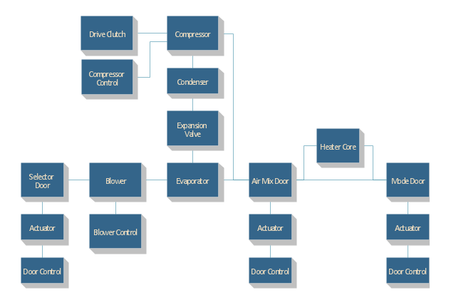
"Automobile air conditioning systems cool the occupants of a vehicle in hot weather, and have come into wide use from the late twentieth century. Air conditioners use significant power; on the other hand the drag of a car with closed windows is less than if the windows are open to cool the occupants evaporatively. There has been much debate on the effect of air conditioning on the fuel efficiency of a vehicle. Factors such as wind resistance, aerodynamics and engine power and weight have to be factored into finding the true variance between using the air conditioning system and not using it when estimating the actual fuel mileage. Other factors on the impact on the engine and an overall engine heat increase can have an impact on the cooling system of the vehicle." [Automobile air conditioning. Wikipedia]
The block diagram example "Automotive HVAC system" was created using the ConceptDraw PRO diagramming and vector drawing software extended with the Block Diagrams solution from the area "What is a Diagram" of ConceptDraw Solution Park.
The block diagram example "Automotive HVAC system" was created using the ConceptDraw PRO diagramming and vector drawing software extended with the Block Diagrams solution from the area "What is a Diagram" of ConceptDraw Solution Park.
Automotive HVAC system
The vector stencil library "HVAC controls" contains contains 24 HVAC control symbols: sensors, actuators, timers, controllers, I/ O points.
Use it for drawing HVAC system diagrams, heating, ventilation, air conditioning, refrigeration, automated building control, and environmental control design floor
plans and equipment layouts.
"HVAC (... Heating, Ventilation and Air Conditioning) is a control system that applies regulation to a heating and/ or air conditioning system. ...
Central controllers and most terminal unit controllers are programmable, meaning the direct digital control program code may be customized for the intended use. The program features include time schedules, setpoints, controllers, logic, timers, trend logs, and alarms. The unit controllers typically have analog and digital inputs that allow measurement of the variable (temperature, humidity, or pressure) and analog and digital outputs for control of the transport medium (hot/ cold water and/ or steam). Digital inputs are typically (dry) contacts from a control device, and analog inputs are typically a voltage or current measurement from a variable (temperature, humidity, velocity, or pressure) sensing device. Digital outputs are typically relay contacts used to start and stop equipment, and analog outputs are typically voltage or current signals to control the movement of the medium (air/ water/ steam) control devices such as valves, dampers, and motors." [HVAC control system. Wikipedia]
The vector stencils example "Design elements - HVAC controls" is included in HVAC Plans solution from the Building Plans area of ConceptDraw Solution
Park.
HVAC control symbols

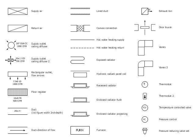
The vector stencil library "HVAC ductwork" contains 63 duct and vent symbols.
Use it for drawing HVAC system diagrams, heating, ventilation, air conditioning, refrigeration, automated building control, and environmental control design floor
plans and equipment layouts.
"Ducts are used in heating, ventilation, and air conditioning (HVAC) to deliver and remove air. These needed airflows include, for example, supply air, return air, and exhaust air. Ducts also deliver, most commonly as part of the supply air, ventilation air. As such, air ducts are one method of ensuring acceptable indoor air quality as well as thermal comfort.
A duct system is often called ductwork. Planning ('laying out'), sizing, optimizing, detailing, and finding the pressure losses through a duct system is called duct design." [Duct (HVAC). Wikipedia]
The vector stencils example "Design elements - HVAC ductwork" is included in HVAC Plans solution from the Building Plans area of ConceptDraw Solution Park.
HVAC ductwork symbols

The vector stencils library "HVAC control equipment" contains 48 HVAC symbols. Use it for drawing HVAC systems diagrams, heating, ventilation, air conditioning, refrigeration, automated building control, and environmental control design building plans and equipment layouts. The symbols example "HVAC control equipment - Vector stencils library" was created using the ConceptDraw PRO diagramming and vector drawing software extended with the HVAC Plans solution from the Building Plans area of ConceptDraw Solution Park.
Duct, sgl line

Duct, dbl line

Return duct, sgl line

Return duct, dbl line

Supply duct, sgl line

Supply duct, dbl line

Return duct 2, sgl line

Return duct 2, dbl line

Supply duct extension, sgl line

Supply duct extension, dbl line

Return duct extension, sgl line

Return duct extension, dbl line

2-fan section, sgl line

2-fan section, dbl line

3-fan section, sgl line

3-fan section, dbl line

4-fan section, sgl line

4-fan section, dbl line

VAV box

DD-VAV box

Fan coil housing

Unit heater

Centrifugal fan

Propeller fan

Vane axial fan

Damper

Filter

Air flow station

Humidifier

Htg/clg coil

Valve

Water flow meter

Pump


Cooling tower

Converter

Heat exchanger

Boiler

Equipment

Starter

VSD

Side to bottom pipe

Side to bottom pipe, arrow
Side to side pipe

Side to side pipe, arrow
Top to bottom pipe

Top to bottom pipe, arrow
Pipe flow arrow
The vector stencils library "HVAC equipment" contains 26 symbols of HVAC equipment. Use it for drawing HVAC system diagrams, heating, ventilation, air conditioning, refrigeration, automated building control and environmental control system layout floor plans in the ConceptDraw PRO diagramming and vector drawing software extended with the HVAC Plans solution from the Building Plans area of ConceptDraw Solution Park.
Rotary pump

Pump

Centrifugal pump

Fan blades, hor.

Fan blades, vert.

Fan blades, 4

Reciprocating pump

Screw pump

Centrifugal fan

Centrifugal fan 2

Axial fan

Axial fan 2

Moisture eliminator

Condenser

Condenser, plate type

Condenser, coil type

Air filter

Dryer

Silencer

Silencer 2

Pipe coil

Pipe coil, fins

Pipe coil, plate

Pipe coil, plate, fins

Refrigerant receiver

Chiller

The vector stencil library "HVAC equipment" contains 84 HVAC equipment symbols as pumps, fans, condensers, pipe coils, silencers, etc.
Use it for drawing HVAC system diagrams, heating, ventilation, air conditioning, refrigeration, automated building control, and environmental control design floor
plans and equipment layouts.
"HVAC (heating, ventilation, and air conditioning) is the technology of indoor and vehicular environmental comfort. HVAC system design is a subdiscipline of mechanical engineering, based on the principles of thermodynamics, fluid mechanics, and heat transfer. Refrigeration is sometimes added to the field's abbreviation as HVAC&R or HVACR, or ventilating is dropped as in HACR (such as the designation of HACR-rated circuit breakers).
HVAC is important in the design of medium to large industrial and office buildings such as skyscrapers and in marine environments such as aquariums, where safe and healthy building conditions are regulated with respect to temperature and humidity, using fresh air from outdoors." [HVAC. Wikipedia]
The vector stencils example "Design elements - HVAC equipment" is included in HVAC Plans solution from the Building Plans area of ConceptDraw Solution Park.
HVAC equipment symbols

The vector stencils library "HVAC ductwork" contains 55 duct and vent symbols of HVAC mechanical components. Use it for drawing HVAC ductwork system diagrams, heating, ventilation, air conditioning, refrigeration, automated building control, and environmental control design in the ConceptDraw PRO diagramming and vector drawing software extended with the HVAC Plans solution from the Building Plans area of ConceptDraw Solution Park.
Rect. duct, closed ends

Rect. duct, open 1 end

Rect. duct, open both ends

Circ. duct, closed ends

Circ. duct, open 1 end

Circ. duct, open both ends

Branch duct, rectangular

Branch duct, circular

Variable bend

Miter bend

Y junction

3 way junction

Junction 1

Beveled junction, rect. duct, rect. branch

Beveled junction, rect. duct, circ. branch

Beveled junction, circ. duct, rect. branch

Beveled junction, circ. duct, circ. branch

Transition, rect. to rect.

Transition, rect. to circ.

Transition, circ. to rect.

Transition, circ. to circ.

Offset transition, rect. to rect.

Offset transition, rect. to circ.

Offset transition, circ. to rect.

Offset transition, circ. to circ.

Flexible connection, rect. duct

Flexible connection, circ. duct

Flexible connection 2, rect. duct

Flexible connection 2, circ. duct

Supply, rect. duct toward

Supply, rect. duct away

Supply, rect. duct, elbow away

Supply, circ. duct toward

Supply, circ. duct away

Supply, circ. duct, elbow away

Return, rect. duct toward

Return, rect. duct away

Return, rect. duct, elbow away

Return, circ. duct toward

Return, circ. duct away

Return, circ. duct, elbow away

Sliding damper, rect. duct

Sliding damper, circ. duct

Damper, ACD

Damper, BD

Damper, FD/AD

Damper, MD

Damper, SD/AD

Vert. duct, rect. duct toward

Vert. duct, rect. duct away

Vert. duct, rect. duct, elbow away

Vert. duct, circ. duct toward

Vert. duct, circ. duct away

Vert. duct, circ. duct, elbow away

VAV box

This HVAC floor plan sample shows the ventilation duct system layout.
"Ducts are used in heating, ventilation, and air conditioning (HVAC) to deliver and remove air. The needed airflows include, for example, supply air, return air, and exhaust air. Ducts commonly also deliver ventilation air as part of the supply air. As such, air ducts are one method of ensuring acceptable indoor air quality as well as thermal comfort.
A duct system is also called ductwork. Planning (laying out), sizing, optimizing, detailing, and finding the pressure losses through a duct system is called duct design." [Duct (flow). Wikipedia]
The HVAC floor plan example "Ductwork layout" was created using the ConceptDraw DIAGRAM diagramming and vector drawing software extended with the HVAC Plans solution from the Building Plans area of ConceptDraw Solution Park.
HVAC floor plan

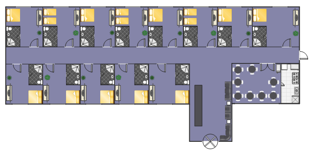
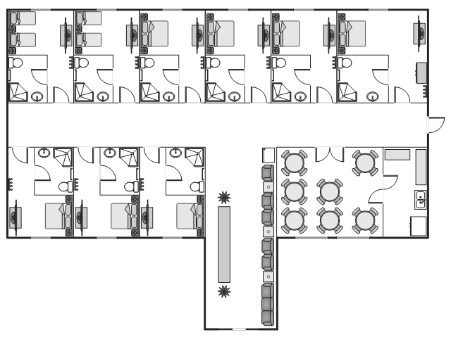
This example depicts furniture and home appliances layout on the hotel floor plan.
"A hotel is an establishment that provides lodging paid on a short-term basis. The provision of basic accommodation, in times past, consisting only of a room with a bed, a cupboard, a small table and a washstand has largely been replaced by rooms with modern facilities, including en-suite bathrooms and air conditioning or climate control. Additional common features found in hotel rooms are a telephone, an alarm clock, a television, a safe, a mini-bar with snack foods and drinks, and facilities for making tea and coffee. Luxury features include bathrobes and slippers, a pillow menu, twin-sink vanities, and jacuzzi bathtubs. Larger hotels may provide additional guest facilities such as a swimming pool, fitness center, business center, childcare, conference facilities and social function services." [Hotel. Wikipedia]
The example "Hotel floor plan" was created using the ConceptDraw PRO diagramming and vector drawing software extended with the Floor Plans solution from the Building Plans area of ConceptDraw Solution Park.
Floor plan
This example depicts furniture and home appliances layout on the hotel floor plan.
"A hotel is an establishment that provides lodging paid on a short-term basis. The provision of basic accommodation, in times past, consisting only of a room with a bed, a cupboard, a small table and a washstand has largely been replaced by rooms with modern facilities, including en-suite bathrooms and air conditioning or climate control. Additional common features found in hotel rooms are a telephone, an alarm clock, a television, a safe, a mini-bar with snack foods and drinks, and facilities for making tea and coffee. Luxury features include bathrobes and slippers, a pillow menu, twin-sink vanities, and jacuzzi bathtubs. Larger hotels may provide additional guest facilities such as a swimming pool, fitness center, business center, childcare, conference facilities and social function services." [Hotel. Wikipedia]
The example "Mini hotel floor plan" was created using the ConceptDraw PRO diagramming and vector drawing software extended with the Basic Floor Plans solution from the Building Plans area of ConceptDraw Solution Park.
Floor plan
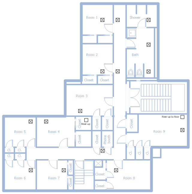
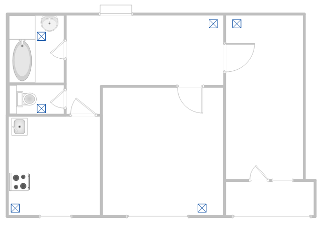
This apartment HVAC (Heating, Ventilating and Air Conditioning) plan shows the layout of exhaust ventilation duct outlet diffusers.
"Ventilation is the intentional introduction of outside air into a space. Ventilation is mainly used to control indoor air quality by diluting and displacing indoor pollutants; it can also be used for purposes of thermal comfort or dehumidification when the introduction of outside air will help to achieve desired indoor psychrometric conditions.
The intentional introduction of outside air can be categorized as either mechanical ventilation, or natural ventilation. Mechanical ventilation uses fans to drive the flow of outside air into a building. This may be accomplished by pressurization (in the case of positively pressurized buildings), or by depressurization (in the case of exhaust ventilation systems). Many mechanically ventilated buildings use a combination of both, with the ventilation being integrated into the HVAC system." [Ventilation (architecture). Wikipedia]
The floor plan example "Apartment HVAC plan" was created using the ConceptDraw DIAGRAM diagramming and vector drawing software extended with the HVAC Plans solution from the Building Plans area of ConceptDraw Solution Park.
Floor plan
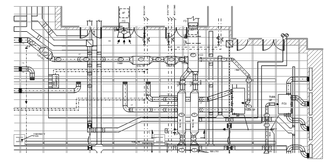
This mechanical systems drawing sample was designed on the base of Wikimedia Commons file: Building services coordinated drawing.JPG.
[commons.wikimedia.org/ wiki/ File:Building_ services_ coordinated_ drawing.JPG ]
This file is licensed under the Creative Commons Attribution-Share Alike 3.0 Unported license. [creativecommons.org/ licenses/ by-sa/ 3.0/ deed.en]
"Mechanical systems drawing is a type of technical drawing that shows information about heating, ventilating, air conditioning and transportation around the building (Elevators or Lifts and Escalator). It is a powerful tool that helps analyze complex systems. These drawings are often a set of detailed drawings used for construction projects; it is a requirement for all HVAC work. They are based on the floor and reflected ceiling plans of the architect. After the mechanical drawings are complete, they become part of the construction drawings, which is then used to apply for a building permit. They are also used to determine the price of the project." [Mechanical systems drawing. Wikipedia]
The mechanical systems drawing example "Building services coordinated drawing" was designed using ConceptDraw DIAGRAM software extended with HVAC Plans solution from the Building Plans area of ConceptDraw Solution Park.
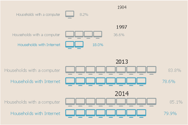
This picture bar graph sample shows the computer and Internet use at home from 1984 to 2014. It was designed using data from website of the United States Census Bureau (USCB).
[census.gov/ content/ dam/ Census/ library/ visualizations/ 2016/ comm/ digital_ nation.png]
"Home automation is the residential extension of building automation and involves the control and automation of lighting, heating, ventilation, air conditioning (HVAC), appliances, and security. Modern systems generally consist of switches and sensors connected to a central hub sometimes called a "gateway" from which the system is controlled with a user interface that is interacted either with a wall-mounted terminal, mobile phone software, tablet computer or a web interface." [Home automation. Wikipedia]
The pictorial chart example "Computer and Internet use at home over time" was created using the ConceptDraw PRO diagramming and vector drawing software extended with the Picture Graphs solution from the Graphs and Charts area of ConceptDraw Solution Park.
Image chart
- Air Conditioner Symbol Floor Plan
- HVAC Plans | How to Create a HVAC Plan | Air handler- HVAC plan ...
- Air Conditioner Switch Symbol
- Mechanical Drawing Symbols | | How to Create a HVAC Plan | Air ...
- Symbol For Electric Cooker Air Condition Switch And Water Heater
- Block diagram - Automotive HVAC system | Automobile Air ...
- Refrigeration And Air Conditioning Engineering Drawing
- Block diagram - Automotive HVAC system | Process Flowchart ...
- Block diagram - Automotive HVAC system | Create Block Diagram ...
- Data Flow Diagram For Air Conditioner Production
- Design elements - HVAC ductwork | Ductwork layout | HVAC Plans ...
- HVAC Plans | How to Create a HVAC Plan | 25 Typical Orgcharts ...
- Heat Ventilation And Air Conditioning System
- Building Design Package | Layout Of Ducting Air Conditioning ...
- Block diagram - Automotive HVAC system | SYSML | Rapid UML ...
- RCP - HVAC layout | HVAC Plans | How to Create a HVAC Plan ...
- Block diagram - Automotive HVAC system | Air Conditioner In Car ...
- HVAC Plans | Er Diagram Of Heating Ventilation Air Condition
- How to Create a HVAC Plan | HVAC Plans | Air handler- HVAC plan ...
- Air Conditioning Switch Symbol