Local area network (LAN). Computer and Network Examples
 diagram")
ConceptDraw - Perfect Network Diagramming Software with examples of LAN Diagrams. ConceptDraw Network Diagram is ideal for network engineers and network designers who need to draw Local Area Network diagrams.

Complete Network Topology

A complete (fully connected) topology is a network topology in which there is a direct link between all pairs of nodes. In a fully connected network with n nodes, there are n(n-1)/2 direct links. Networks designed with this topology are usually very expensive to set up, but provide a high degree of reliability due to the multiple paths for data that are provided by the large number of redundant links between nodes.
Electrical Symbols — Transmission Paths
26 libraries of the Electrical Engineering Solution of ConceptDraw DIAGRAM make your electrical diagramming simple, efficient, and effective. You can simply and quickly drop the ready-to-use objects from libraries into your document to create the electrical diagram.
Flow Chart Symbols

Flowchart diagrams consists of symbols of process, decision, data and document, data base, termination or initiation processes, processing loops and conditions. To create an drawn flowchart use professional flowchart maker of ConceptDraw DIAGRAM.
Electrical Symbols, Electrical Diagram Symbols

This solution provides 26 libraries which contain 926 electrical symbols from electrical engineering: Analog and Digital Logic, Composite Assemblies, Delay Elements, Electrical Circuits, Electron Tubes, IGFET, Inductors, Integrated Circuit, Lamps, Acoustics, Readouts, Logic Gate Diagram, MOSFET, Maintenance, Power Sources, Qualifying, Resistors, Rotating Equipment, Semiconductor Diodes, Semiconductors, Stations, Switches and Relays, Terminals and Connectors, Thermo, Transformers and Windings, Transistors, Transmission Paths,VHF UHF SHF.
Calculate the cost of creating or updating a wireless computer network
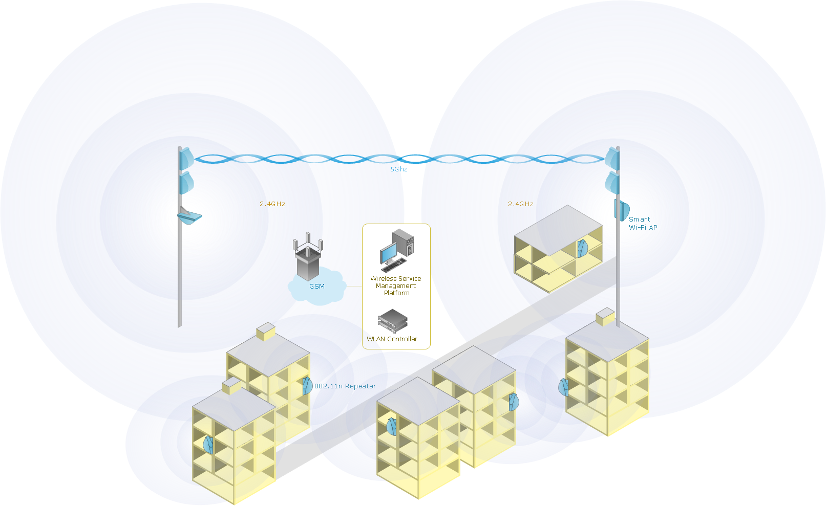
Drawing some wireless computer network as it may be a challenge, especially for those who do not have as much experience of doing it. That is why the CS Odessa team has developed the Wireless Networks solution so it can be used for simplifying all the ConceptDraw DIAGRAM users work on the needed diagrams.
Electrical Drawing Software and Electrical Symbols

Electrical Drawing Software provides the 26 stencils libraries of ready-to-use predesigned vector electrical symbols, templates and samples that make your electrical drawing quick, easy and effective.
Electrical Symbols — Switches and Relays

26 libraries of the Electrical Engineering Solution of ConceptDraw DIAGRAM make your electrical diagramming simple, efficient, and effective. You can simply and quickly drop the ready-to-use objects from libraries into your document to create the electrical diagram.
How To use Landscape Design Software

ConceptDraw DIAGRAM diagramming and vector drawing software extended with Landscape & Garden Solution offers powerful drawing tools and numerous collection of pre-designed vector objects for effective landscape design, landscape plans, deck plans, patio plans, floor plans.
Network Glossary Definition

Easy to draw network topology diagrams, network mapping and Cisco network topology.
- Light Path Topology Design Diagram
- Bus network topology diagram | Transmission paths - Vector stencils ...
- Network Diagram Examples | Telecommunication Network ...
- Communication medium diagram | Design elements - Transmission ...
- Wireless Network Topology | Hotel Network Topology Diagram ...
- Odf Optic Fiber Network Diagram Symbol
- Network Layout Floor Plans | Local area network (LAN). Computer ...
- The Best Choice for Creating Diagram | Concept Mapping ...
- Wiring Diagrams with ConceptDraw PRO | How To use House ...
- Design elements - Electrical circuits
- ERD | Entity Relationship Diagrams, ERD Software for Mac and Win
- Flowchart | Basic Flowchart Symbols and Meaning
- Flowchart | Flowchart Design - Symbols, Shapes, Stencils and Icons
- Flowchart | Flow Chart Symbols
- Electrical | Electrical Drawing - Wiring and Circuits Schematics
- Flowchart | Common Flowchart Symbols
- Flowchart | Common Flowchart Symbols