Made with
ConceptDraw
DIAGRAM 18

Calculate the cost of creating or updating
a wireless computer network

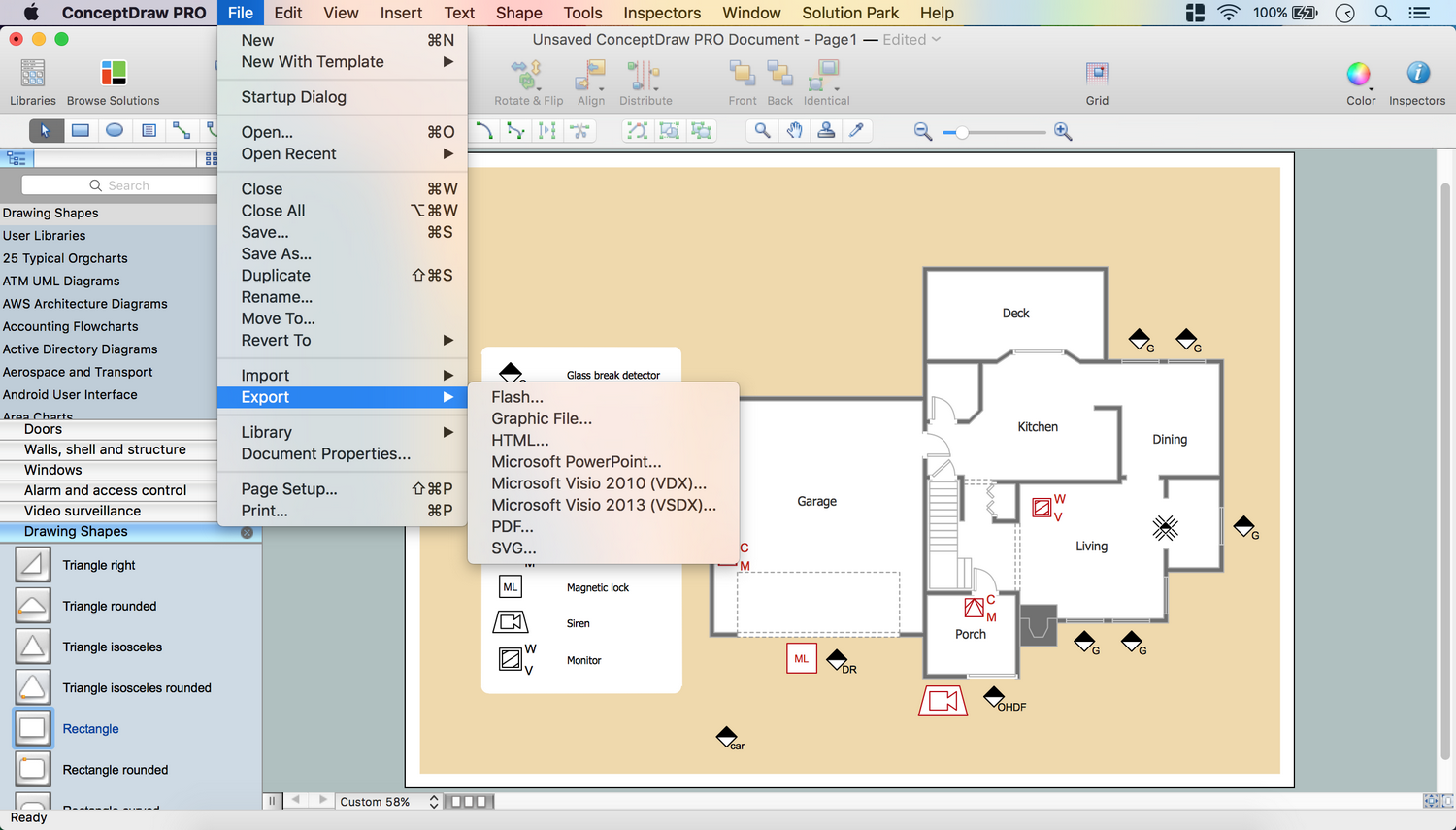
Working for IT company sometimes there is a need for drawing a Wireless Network diagram arises. It is always possible to create any needed Wireless Network diagram with the help of ConceptDraw DIAGRAM diagraming and drawing software as well as another product of CS Odessa — the ConceptDraw STORE application and the Wireless Networks solution in particular.

Any wireless network is some computer network that can use any needed wireless data connections that can be placed between the network nodes. Any wireless networking is known to be one of the methods by which both telecommunications networks and business installations, same as the homes avoid the process of introducing the cables into some building.

Wireless Computer Network Solution

Sample 1. Wireless Computer Network Diagram Solution

There may be a need in making the connections between many different equipment locations and, again, the wireless telecommunications networks can help with replacing the old methods, being implemented as well as administered by using the radio communication. The mentioned implementation is known to be taking place at the physical level of the OSI model network structure and it is a common way to solve the existing problems.

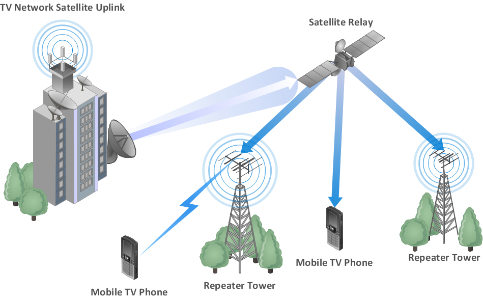
There may be many different examples of the wireless networks that may include wireless local area networks, cell phone networks, wireless sensor networks, terrestrial microwave networks and satellite communication networks. All the possible types of the wireless networks are explained below.

Thus, there are so-called “Wireless PANs” which are simply the “wireless personal area networks” internet devices within some small area. Next, there are the wireless LANs that are often used for connecting to some local resources as well as to the Internet. Any wireless local area network is known to be linking two or more devices over some short distance by using a so-called “wireless distribution method”.

Usually, the previously mentioned process can be done by providing the needed connection through some access point to get some internet access. The use of either OFDM or spread-spectrum technologies may allow the users to move around within some particular local coverage area, remaining connected to the network at the same time.

There are many products that are known to be using the so-called “IEEE 802.11 WLAN standards”, being marketed under the “Wi-Fi” brand name. Thus, a fixed wireless technology is known to be implementing the so-called “point-to-point links” between different networks or computers at two distant locations by using the modulated laser light beams over a line of sight paths, or the dedicated microwave. The mentioned method can be often found to be used in big cities in order to connect the networks in two or more buildings with no need of installing some wired link.

Next, a wireless ad hoc network. The mentioned type of the wireless computer network can be also known to be called as a “mobile ad hoc network” (or MANET) or “wireless mesh network”, being a wireless network that is made up of some radio nodes that were previously organized in some mesh topology.

Each of the described nodes can forward the needed messages on behalf of the other nodes. At the same time, each of the nodes can perform the routing. Ad hoc networks can automatically re-routing around some particular node that has already lost its power.

Different network layer protocols are those which can help realize the ad hoc mobile networks, such as the following ones: Associativity-Based Routing, Distance Sequenced Distance Vector routing, Dynamic source routing and Ad hoc on-demand Distance Vector routing.

The wireless metropolitan area networks are also very popular being a type of wireless network that connects a few wireless LANs. A so-called WiMAX is one of the types of the Wireless MAN, being described by the “IEEE 802.16” standard.

Wireless wide area networks or Wireless WANs are simply the wireless networks that can cover some large areas, such as between cities and towns that are located close to each other, or the suburbs and city. The mentioned networks can be used for connecting all the needed branch offices of business. Also, they can be used as a public Internet access system.

The wireless connections that are placed between different access points can be the so-called “point to point microwave links” using parabolic dishes on the 2.4 GHz band. But not the omnidirectional antennas that are used with some smaller networks. Any system that contains the “base station gateways”, “wireless bridging relays” and “access points” can be a wireless connection.

Other configurations are called as the “mesh systems” having each of the access points acting as a relay also. Once the described systems are combined with the renewable energy systems (e.g., wind systems or photovoltaic solar panels), they can be called as the “stand-alone” ones.

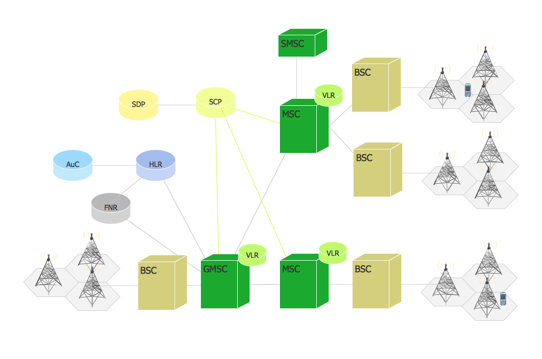
There is also such term as the “Global System for Mobile Communications”, or GSM. Any GSM network is known to be divided into three main systems: the switching system, the operation and support system and the base station system. Any cell phone can connect to any needed base system station which then can connect to the support and the operation station. Connecting to the switching station where the call is known to be transferred to where it needs to go, the GSM is one of the most common standards widely used for most of the cell phones.

Calculate the cost of creating or updating <br>a wireless computer network *

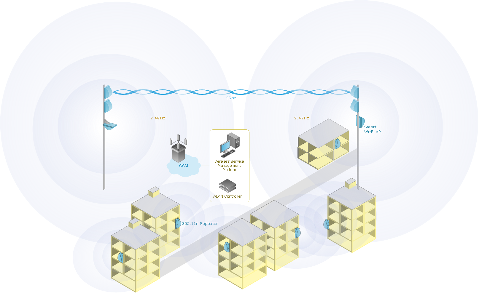
Sample 1. Wireless network diagram: Mobile data offloading

Drawing some wireless computer network as it may be a challenge, especially for those who do not have as much experience of doing it. That is why the CS Odessa team has developed the Wireless Networks solution so it can be used for simplifying all the ConceptDraw DIAGRAM users work on the needed diagrams.

TEN RELATED HOW TO's:
When you need to visually represent the structure of relational database, Entity relationship diagram (ERD) is a type of diagram for that case. Most entity-relationship diagrams can be built with objects from Flowchart solution or ERD Solution which contains inbuilt templates. Follow these steps to create your own custom ERD diagram. Don't be frightened if it looks complex, ConceptDraw DIAGRAM makes it easy to create an ERD, and hundreds of other diagrams, in minutes.Developing Entity Relationship Diagrams *
Picture: Developing Entity Relationship Diagrams
Related Solution:
Another stencil library that is included in the Computer Network Diagrams solution is the “Computer Network” one. It includes such design symbols as the representation of the Desktop computer, HP desktop computer, Workstation, HP workstation, iMac, HP laptop, Fujitsu laptop, MacBook, MacBook Air, MacBook Pro, Computer monitor, Apple Thunderbolt Display, Mac Pro, iPad mini, iPhone 4, iPhone 5, iPhone / iPod Touch, iPod Classic, PDA, Smartphone, Mobile Phone, Mainframe, City, Satellite dish, Radio tower, Satellite, Cloud, Data store, Compact disk, Curved bus, Comm-disk, Token-ring, FDDI Ring, Star, Ethernet and bus.Active Directory Network. Computer and Network Examples *
Picture: Active Directory Network. Computer and Network Examples
Related Solution:
When studying a business process or system involving the transfer of data, it is common to use a Data Flow Diagram (DFD) to visualize how data are processed. Being initially used exclusively in regards to the flow of data through a computer system, now DFDs are employed as the business modeling tools. They are applied to describe the business events and interactions, or physical systems involving data storage and transfer. ConceptDraw DIAGRAM is a powerful Data Flow Diagram software thanks to the Data Flow Diagrams solution from the Software Development area of ConceptDraw Solution Park.Data Flow Diagram Software *
Picture: Data Flow Diagram Software
Related Solution:
A cozy atmosphere is crucial for the success of any cafe or restaurant. To provide it, you should use restaurant floor plan software at the stage of design. If your establishment is located conveniently and has a harmonic atmosphere inside it, this is bound to be a success. This sample Restaurant floor plan illustrates the possibilities of ConceptDraw solution for Cafe and Restaurant plans. It represents the location of the restaurant's main hall with its furnishing as well as a plan of kitchen and toilets. Generally, Cafe and Restaurant Plans solution has a big set vector images of tables, seats, lightening, etc. Using them you will be able to plan the restaurant of your desire with an incredible design and spirit.Restaurant Floor Plan Software
Picture: Restaurant Floor Plan Software
Related Solution:
How should diagramming software work? Is it possible to develop a diagram as quickly as the ideas come to you? The innovative ConceptDraw Smart Connectors Technology - This is more than enough versatility to draw any type of diagram with any degree of complexity. Connection points are necessary for diagramming network, flowchart and organizational charts. In ConceptDraw you connect shapes by attaching, or snapping and gluing, connectors to shape connection points.ConceptDraw Arrows10 Technology *
Picture: ConceptDraw Arrows10 Technology
Talking about companies, that have influenced the entire industry, we should mention Cisco and it’s influence on network design. Nowadays, this equipment has became a kind of standard, and Cisco icons, shapes, stencils, symbols and design elements are easily recognized among others. You can use these icons to develop a network diagram of any complexity. When dealing with creating a pack of network documentation, system administrator often have to depict a network containing a network equipment of such a well-known manufacturer as Cisco. As Cisco has developed its own production standard icons that are strongly recommended to use in Cisco network diagrams. The best way to draw Cisco Network diagram Cisco certified icons is using ConceptDraw solution for Cisco Network Diagrams. Using Cisco symbols library provided by this solution allows system administrator, or network architect to design a prototype of a new network or document an existing one.Cisco Network Design. Cisco icons, shapes, stencils, symbols and design elements *
Picture: Cisco Network Design. Cisco icons, shapes, stencils, symbols and design elements
Related Solution:
Whenever you need quick presentations, the ability to choose specific content, the ability to focus on specific stakeholder needs, update data, or create polished slide decks — ConceptDraw MINDMAP provides a presentation solution for you.Presentation Preparation using Mind Maps *
Picture: Presentation Preparation using Mind Maps
Related Solution:
Any business process consists from a number of tasks carrying out the certain business goal. It is useful to diagram business processes to ensure that they are as foolproof, logical and sequential as possible. This business process diagram describes a typical booking process flow by the example of a cab booking process. It can be used as a roadmap for any booking system implementation. Diagramming a business process allows you to look at the entire project and take into account all types of possible scenarios. Business process diagram helps you investigate and clarify the process thoroughly so that you can find out how it can be improved. Business process diagram supports team communications by ensuring that each process element is clear and everyone in the team is on the same page. Sometimes your company brings you less profit than you expect it to be, and it’s difficult to reveal the causes. Maybe it’s time to learn new technologies, because business diagram are easily developed by means of special software, so you won’t make any extra effort. In return, you will increase your productivity and get more done in a less time.Business Diagram Software *
Picture: Business Diagram Software
Related Solutions:
This sample was created in ConceptDraw DIAGRAM diagramming and vector drawing software using the Flowcharts solution from the Diagrams area of ConceptDraw Solution Park. This sample shows the Flowchart of the Subprime Mortgage Crisis. This Flowchart describes the decline in housing prices when the housing bubble burst and what it caused on the housing and financial markets. You can also see the Government and Industry responses in this crisis situation.Flowchart on Bank. <br>Flowchart Examples *
Picture: Flowchart on Bank. Flowchart Examples
Related Solution:
An inductor, also called a coil or reactor, is a passive two-terminal electrical component which resists changes in electric current passing through it. It consists of a conductor such as a wire, usually wound into a coil. Energy is stored in a magnetic field in the coil as long as current flows. When the current flowing through an inductor changes, the time-varying magnetic field induces a voltage in the conductor, according to Faraday’s law of electromagnetic induction. 26 libraries of the Electrical Engineering Solution of ConceptDraw DIAGRAM make your electrical diagramming simple, efficient, and effective. You can simply and quickly drop the ready-to-use objects from libraries into your document to create the electrical diagram.Electrical Symbols — Inductors *
Picture: Electrical Symbols — Inductors
Related Solution:
ConceptDraw
DIAGRAM 18