 Fishbone Diagrams
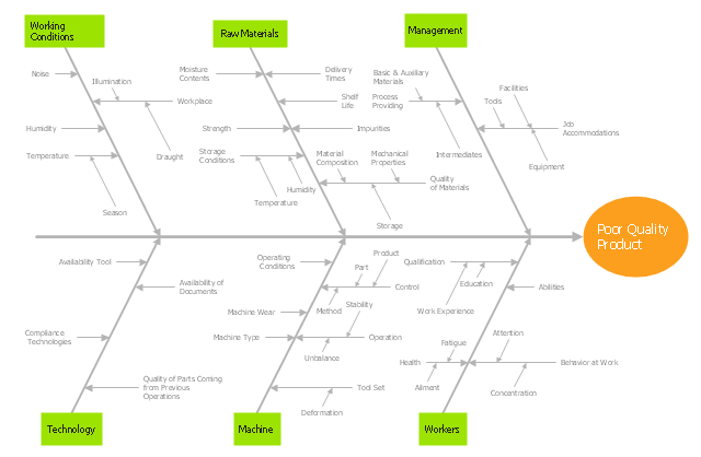
The Fishbone Diagrams solution extends ConceptDraw PRO v10 software with the ability to easily draw the Fishbone Diagrams (Ishikawa Diagrams) to clearly see the cause and effect analysis and also problem solving. The vector graphic diagrams produced using this solution can be used in whitepapers, presentations, datasheets, posters, and published technical material.
Example of DFD for Online Store (Data Flow Diagram) DFD Example


Planogram Software and Retail Plan Software

"Ishikawa diagrams (also called fishbone diagrams, herringbone diagrams, cause-and-effect diagrams, or Fishikawa) are causal diagrams created by Kaoru Ishikawa (1968) that show the causes of a specific event. Common uses of the Ishikawa diagram are product design and quality defect prevention, to identify potential factors causing an overall effect. Each cause or reason for imperfection is a source of variation. Causes are usually grouped into major categories to identify these sources of variation. The categories typically include:
- People: Anyone involved with the process
- Methods: How the process is performed and the specific requirements for doing it, such as policies, procedures, rules, regulations and laws
- Machines: Any equipment, computers, tools, etc. required to accomplish the job
- Materials: Raw materials, parts, pens, paper, etc. used to produce the final product
- Measurements: Data generated from the process that are used to evaluate its quality
- Environment: The conditions, such as location, time, temperature, and culture in which the process operates" [Ishikawa diagram. Wikipedia]
The fishbone diagram example "Causes of low-quality output" was created using the ConceptDraw PRO diagramming and vector drawing software extended with the Fishbone Diagrams solution from the Management area of ConceptDraw Solution Park.
Ishikawa diagram
 Entity-Relationship Diagram (ERD)
Entity-Relationship Diagram (ERD) solution extends ConceptDraw PRO software with templates, samples and libraries of vector stencils from drawing the ER-diagrams by Chen's and crow’s foot notations.
What Is Information Architecture

Process Flowchart


 Circle-Spoke Diagrams
Examples of subject areas that are well suited to this approach are marketing, business, products promotion, process modeling, market, resource, time, and cost analysis. Circle-Spoke Diagrams are successfully used in presentations, conferences, management documents, magazines, reportages, reviews, reports, TV, and social media.
 Business Process Mapping
The Business Process Mapping solution for ConceptDraw PRO is for users involved in process mapping and creating SIPOC diagrams.
 SWOT and TOWS Matrix Diagrams
SWOT and TOWS Matrix Diagrams solution extends ConceptDraw PRO and ConceptDraw MINDMAP software with features, templates, samples and libraries of vector stencils for drawing SWOT and TOWS analysis matrices and mind maps.
Affinity Diagram

 Flowcharts
The Flowcharts solution for ConceptDraw PRO is a comprehensive set of examples and samples in several varied color themes for professionals that need to represent graphically a process. Solution value is added by the basic flow chart template and shapes' libraries of flowchart notation. ConceptDraw PRO flow chart creator lets one depict the processes of any complexity and length, as well as design the Flowchart either vertically or horizontally.
SWOT Matrix Template

Onion Diagram Maker

- Fishbone Diagrams | Process Flowchart | Fishbone Diagram ...
- Fishbone Diagrams | Fishbone Diagram | Enterprise Architecture ...
- Business Process Modeling Notation Template | Fishbone Diagram ...
- Fishbone Diagrams | How to Construct a Fishbone Diagram | Café ...
- Fishbone Diagram | Fishbone Diagrams | Improving Problem ...
- Store Layout Software | Example of DFD for Online Store (Data Flow ...
- Sales Flowcharts | Competitor Analysis | Fishbone Diagrams | Iso ...
- Example of DFD for Online Store (Data Flow Diagram ) DFD ...
- How Do Fishbone Diagrams Solve Manufacturing Problems | Draw ...
- Example of DFD for Online Store (Data Flow Diagram ) DFD ...
- Retail Management Charts And Diagram
- Store Layout Software | Process Flowchart | Planogram | Retail Store ...
- Flow Chart Of B2b Marketing
- Retail Store Process Flow Chart
- Example of DFD for Online Store (Data Flow Diagram ) DFD ...
- Fishbone Diagrams | Competitor Analysis | Status Dashboard ...
- UML interaction overview diagram - Online shopping | Example of ...
- Manufacturing 8 Ms fishbone diagram - Template | Bar Diagrams for ...
- Store Layout Software | Planogram Software and Retail Plan ...
- UML Component Diagram Example - Online Shopping | State ...