Simple & Fast Diagram Software

Software Diagram Examples and Templates

UML Class Diagram Example for Transport System
ConceptDraw Arrows10 Technology
How to Draw ER Diagrams

Fishbone Diagram Example

Online Diagram Tool
ConceptDraw Arrows10 Technology
 Food Court
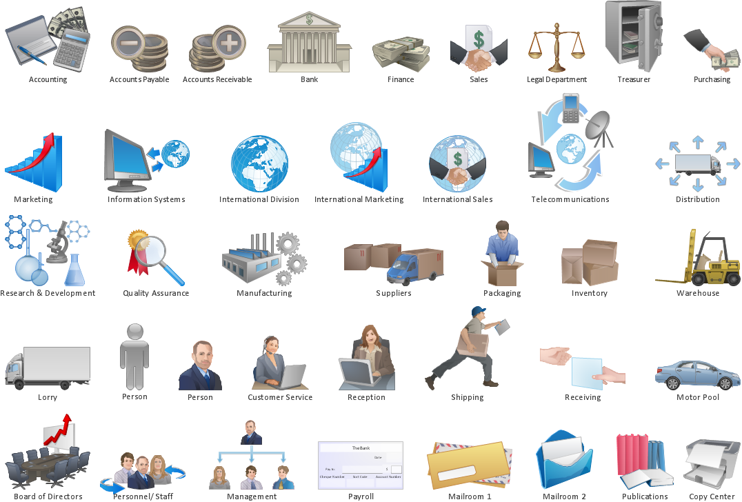
Use the Food Court solution to create food art. Pictures of food can be designed using libraries of food images, fruit art and pictures of vegetables.
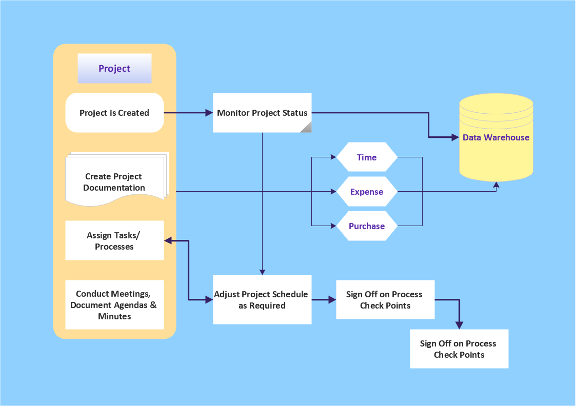
How to Draw Workflow Diagram
ERD Symbols and Meanings


Data Flow Diagram

Diagram Flow Chart
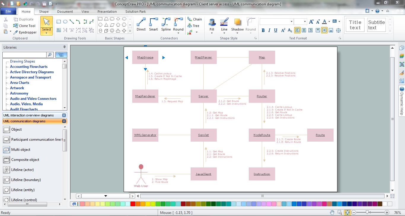
UML Collaboration Diagram Example Illustration

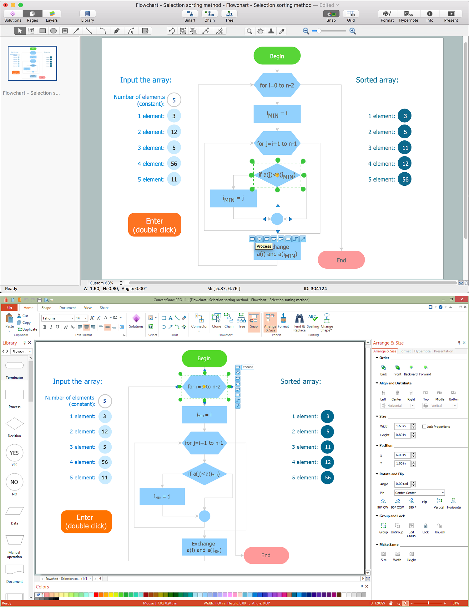
Processing Flow Chart

ConceptDraw DIAGRAM enhanced with Flowcharts Solution from the "Diagrams" Area of ConceptDraw Solution Park is a powerful Processing Flow Chart software which will help save lots of your time.
- Simple & Fast Diagram Software | Software Diagram Examples and ...
- Create Block Diagram | Software Diagram Examples and Templates ...
- Cooking Recipes | Simple & Fast Diagram Software | Flow chart ...
- Simple & Fast Diagram Software | The Best Flowchart Software ...
- Processing Flow Chart | Simple & Fast Diagram Software | Entity ...
- Simple & Fast Diagram Software | Software Diagram Examples and ...
- Simple & Fast Diagram Software | Software Diagram Examples and ...
- Simple & Fast Diagram Software | Software Diagram Examples and ...
- Software Diagram Examples and Templates | Food Court | Simple ...
- Software Diagram Examples and Templates | Simple & Fast ...
- Simple & Fast Diagram Software | Mathematical Diagrams | Pyramid ...
- Software Diagram Examples and Templates | Simple & Fast ...
- Flow chart Example . Warehouse Flowchart | Simple & Fast Diagram ...
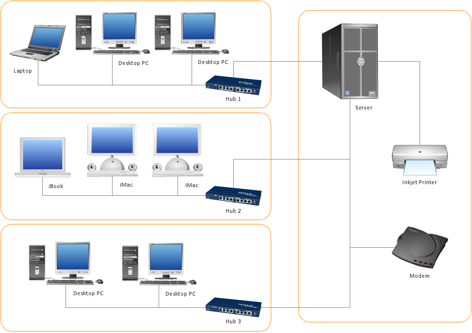
- Basic Network Diagram | Software Diagram Examples and ...
- Simple & Fast Diagram Software | ConceptDraw Arrows10 ...
- Fast Diagram Example
- UML Class Diagram Example for Transport System | Simple & Fast ...
- Fast Diagram Examples For 5 Star Hotel
- Simple & Fast Diagram Software | ConceptDraw Arrows10 ...