Processing Flow Chart
Introduction to Processing Flow Charts
Flowcharts are graphical representations of algorithms, processes, or step-by-step solutions to problems. There are many different types of Flowcharts, among them Process Flowcharts, Data Processing Flowchart, Cross-Functional Flowcharts, Data Flow Diagrams, IDEF Flowcharts, Workflow Diagrams, and many others. They have a special value when you need to represent a complex process, depict in detail the process of solving problems, efficiently plan, and set the tasks priorities. Flowcharts need to be constructed briefly, clearly, and logically, simplifying the process or procedure, and making easier the comprehension and perception of information.
Processing Flow Chart is a simplified sketch that is used in chemical and process engineering to illustrate general plant streams, major equipment, and key control loops. ConceptDraw DIAGRAM software enhanced with the Flowcharts Solution from the Diagrams area of ConceptDraw Solution Park is a powerful Processing Flow Chart software that saves lots of your time when drawing Process flowcharts, Process flow diagrams, Workflow diagrams, and other types of Flowcharts and technical illustrations for business documents and other purposes. Easier defining and documenting basic work and data flows, financial, production, and quality management processes to increase the efficiency of your business with ConceptDraw DIAGRAM business process mapping software.

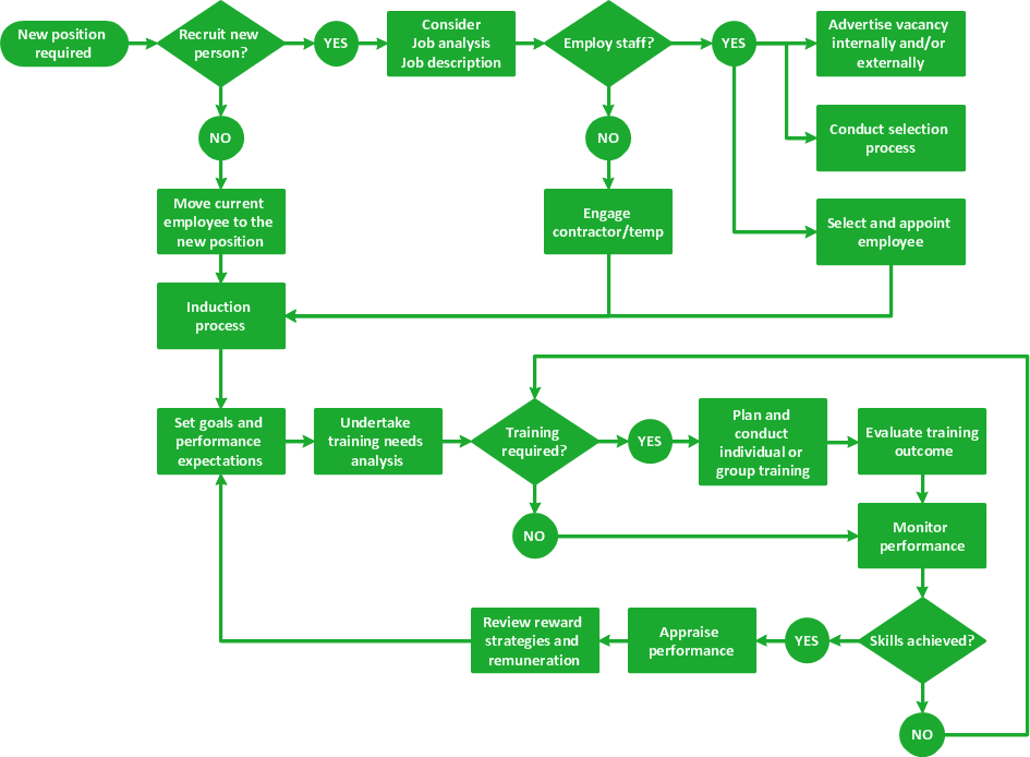
Example 1. Payment Processing Flowchart Example — Invoice Processing Flowchart
Benefits of Using Processing Flow Charts
The Processing Flow Chart has a wide set of benefits:
- gives a clear documentation of a process;
- allows to define and offers a common understanding of processes;
- helps to build a process visual representation for analysis, discussion, and communication;
- allows to identify the scope of the process;
- helps in tracing and analyzing the process steps;
- helps to standardize and find areas for monitoring, improvement, and increased efficiency in a process;
- allows to find and detach the steps of the process that are not essential;
- helps in understanding the logic of complex problems;
- offers guidance for managers overseeing operations;
- shows the plant design basis, the arrangement of major equipment, process lines, and main control loops;
- indicates feedstock, product, main streams, flow rates, and operating conditions;
- facilitates communication between programmers and business people;
- helps programmers to write programs of any complexity and in any high-level language;
- helps in the debugging process and provides efficient program maintenance;
- helps to understand and explain to other people the logic of the complex problems and their solution;
- assists in improving teamwork efficiency.

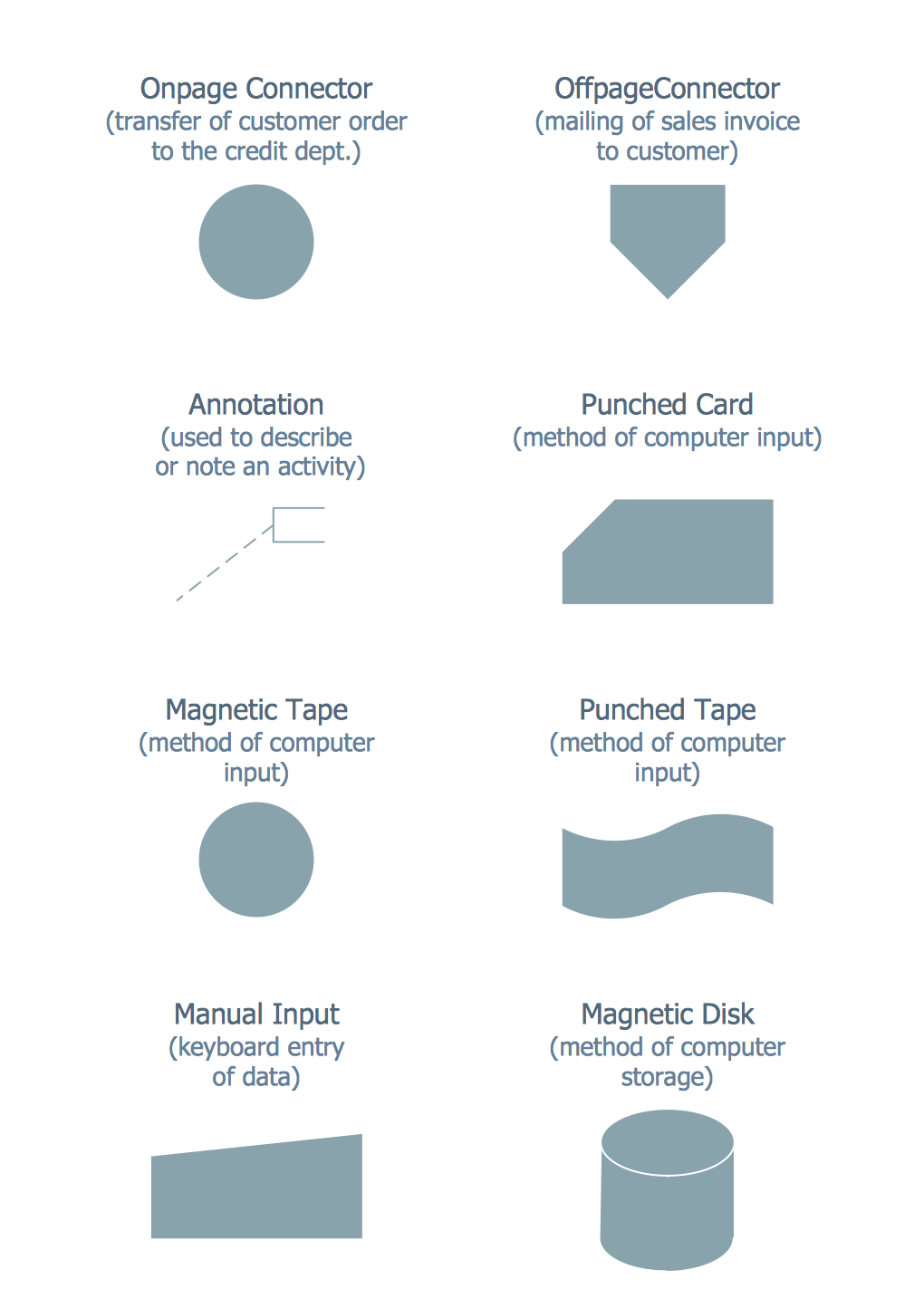
Example 2. Processing Flow Chart. Design Elements — Order Processing for Apple OS X and Windows
Processing Flow Charts in Software Development
One of the applications of Processing Flow Charts is software development. They are a first step on the way to coding and help to:
- represent the algorithm and explain it to stakeholders;
- visualize the logic, structure, and flow of a program or algorithm;
- explain logic of a program, show data flow, organization and execution of code;
- map out algorithms, outline the steps in a process before coding;
- identify logical errors, inefficiencies or mistakes in logic;
- communicate ideas, share design or logic concepts with team members;
- easier understanding, design, and debugging programs;
- show the structure of a website or a program;
- test the code and fix bugs;
- analyze the navigation of users through websites or applications;
- plan, analyze, and improve system design;
- track the Agile development cycles, identify areas for improvement, detect delays and bottlenecks;
- analyze and optimize software development process to reduce errors, improve consistency, enhance efficiency, and increase customer satisfaction.
Processing Flow Chart Design in ConceptDraw DIAGRAM Software
ConceptDraw DIAGRAM flowchart app enhanced with Flowcharts solution from the Diagrams area of ConceptDraw Solution Park is a powerful business process mapping software and flowchart maker, which simplifies your work. It includes extensive drawing tools, rich examples and templates, processing flowchart symbols, shape libraries, and smart connectors that allow you to create Flowcharts of simple or complex processes, Process flow diagrams, procedures, and easier communication and information exchange.
To create the Process Flow Diagram, the process is following: first of all, you have to open a ConceptDraw DIAGRAM new document and select one of the existing libraries (we have chosen the BPMN one this time for the diagram illustrated on our site page). Then you have to add BPMN elements to the diagram by dragging them from the library to the document page. Add the next object by clicking on its icon from the RapidDraw arrows that pop up when you bring the mouse cursor over the object. Modify objects any time you need by using their Action button menu.
See how simple it is to use this software and how useful are all the pre-made design elements as well as pre-made examples. Try to make a Process Flowchart or one of the needed Flowcharts and diagrams of other types yourself and realize how convenient and unique this product is.
Typically a Flowchart has a sufficiently great size, but for ConceptDraw DIAGRAM it's not a problem. Now, you don't need to think about Flowchart size, you can design arbitrarily large Flowcharts. If your chart does not fit the document size, if it is bigger than the document, use the Fit to Content tool to automatically resize the page according to the size of the Flowchart on it.
Don't forget to add comments and additional information near the chart, they allow making your Flowcharts more informative and useful.

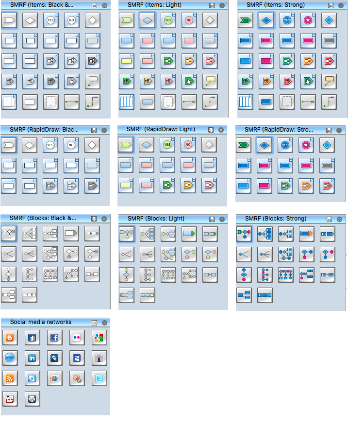
Example 3. Flowcharts Solution in ConceptDraw STORE
Examples
A large collection of predesigned samples included in Flowcharts solution deserves special attention. It is conveniently represented in ConceptDraw STORE. Having a huge variety of samples and templates for making your unique great-looking Flowcharts, any type, size, color, and shape, seems to be a good thing to get. Planning a new project, representing some algorithm or some process, illustrating a solution to a given problem, representing process operations, analyzing, designing, documenting, or managing a process in various fields is always better to do in a way of Flowchart, and the types of Flowcharts and diagrams are numerous.
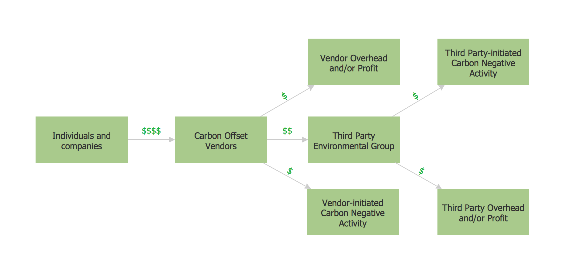
The samples you see on this page were created in ConceptDraw DIAGRAM software using the predesigned shapes from the libraries of Flowcharts solution. These samples successfully demonstrate the solution's capabilities and the professional results you can achieve. An experienced user spent 10 minutes creating each of them. Use the tools of Flowcharts solution for effective Processing Diagram design and easy creating professional-looking Flow Process Charts.
All source documents are vector graphic documents. They are available for reviewing, modifying, or converting to a variety of formats (PDF file, MS PowerPoint, MS Visio, and many other graphic formats) from the ConceptDraw STORE.
Conclusion
Flowcharts solution for ConceptDraw DIAGRAM software is so helpful thanks to the powerful drawing tools and set of libraries with numerous ready-to-use vector objects developed especially for ConceptDraw DIAGRAM users.
Each Processing Flow Chart sample included in the Flowcharts solution for ConceptDraw DIAGRAM application is a carefully thought-out example, a perfect base for drawing your own Process Flow Diagram, and an excellent source of inspiration!