"A hydraulic circuit is a system comprising an interconnected set of discrete components that transport liquid. The purpose of this system may be to control where fluid flows (as in a network of tubes of coolant in a thermodynamic system) or to control fluid pressure (as in hydraulic amplifiers).
... hydraulic circuit theory works best when the elements (passive component such as pipes or transmission lines or active components such as power packs or pumps) are discrete and linear. This usually means that hydraulic circuit analysis works best for long, thin tubes with discrete pumps, as found in chemical process flow systems or microscale devices." [Hydraulic circuit. Wikipedia]
The engineering drawing example "Hydraulic circuits" was redrawn using ConceptDraw PRO diagramming and vector drawing software from the Wikimedia Commons file: Hydraulic circuits.png.
[commons.wikimedia.org/ wiki/ File:Hydraulic_ circuits.png]
This file is licensed under the Creative Commons Attribution-Share Alike 3.0 Unported license.
[creativecommons.org/ licenses/ by-sa/ 3.0/ deed.en]
The engineering drawing example "Hydraulic circuits" is included in the Mechanical Engineering solution from the Engineering area of ConceptDraw Solution Park.
Hydraulic circuit schematic

Mechanical Drawing Symbols

The vector stencils library "Fluid power equipment" contains 113 symbols of hydraulic and pneumatic equipment including pumps, motors, air compressors, cylinders, meters, gauges, and actuators.
Use it to design fluid power and hydraulic control systems in the ConceptDraw PRO diagramming and vector drawing software extended with the Mechanical Engineering solution from the Engineering area of ConceptDraw Solution Park.
www.conceptdraw.com/ solution-park/ engineering-mechanical
Use it to design fluid power and hydraulic control systems in the ConceptDraw PRO diagramming and vector drawing software extended with the Mechanical Engineering solution from the Engineering area of ConceptDraw Solution Park.
www.conceptdraw.com/ solution-park/ engineering-mechanical
Actuator (semi-rotary), pneumatic
,-pneumatic-fluid-power-equipment---vector-stencils-library.png--diagram-flowchart-example.png)
Actuator (semi-rotary), hydraulic
,-hydraulic-fluid-power-equipment---vector-stencils-library.png--diagram-flowchart-example.png)
Drive unit, pneumatic

Drive unit, hydraulic

Sgl-act. cylinder, pneum., left spring

Sgl-act. cylinder, pneum., right spring

Sgl-act. cylinder, pneumatic

Sgl-act. cylinder, hydr., left spring

Sgl-act. cylinder, hydr., right spring

Sgl-act. cylinder, hydraulic

Dbl-act. cylinder, pneumatic

Dbl-act. cylinder, pneum., sgl cushion

Dbl-act. cylinder, pneum., dbl cushion

Dbl-act. cylinder, pneum., adjustable

Dbl-act. cylinder, pneum., sgl cushion, adj.

Dbl-act. cylinder, pneum., dbl cushion, adj.

Dbl-act. cylinder, hydraulic

Dbl-act. cylinder, hydr., sgl cushion

Dbl-act. cylinder, hydr., dbl cushion

Dbl-act. cylinder, hydr., adjustable

Dbl-act. cylinder, hydr., sgl cushion, adj.

Dbl-act. cylinder, hydr., dbl cushion, adj.

Dbl-act. cylinder, magnetic

Dbl-act. cylinder, magn., sgl cushion

Dbl-act. cylinder, magn., dbl cushion

Dbl-act. cylinder, magn., adjustable

Dbl-act. cylinder, magn., sgl cushion, adj.

Dbl-act. cylinder, magn., dbl cushion, adj.

Dbl-act. dbl-end. cylinder, pneumatic

Dbl-act. dbl-end. cylinder, pneum., sgl cushion

Dbl-act. dbl-end. cylinder, pneum., dbl cushion

Dbl-act. dbl-end. cylinder, pneum., adjustable

Dbl-act. dbl-end. cylinder, pneum., sgl cushion, adj.

Dbl-act. dbl-end. cylinder, pneum., dbl cushion, adj.

Dbl-act. dbl-end. cylinder, hydraulic

Dbl-act. dbl-end. cylinder, hydr., sgl cushion

Dbl-act. dbl-end. cylinder, hydr., dbl cushion

Dbl-act. dbl-end. cylinder, hydr., adjustable

Dbl-act. dbl-end. cylinder, hydr., sgl cushion, adj.

Dbl-act. dbl-end. cylinder, hydr., dbl cushion, adj.

Telescopic cylinder, pneum., dbl-act.

Telescopic cylinder, hydr., dbl-act.

Telescopic cylinder, pneum., sgl-act.

Telescopic cylinder, hydr., sgl-act.

Actuator, hydraulic-pneumatic

Actuator, pneumatic-hydraulic

Intensifier, pneumatic

Intensifier, hydraulic

Intensifier, hydraulic-pneumatic

Intensifier, pneumatic-hydraulic

Intensifier, pneumatic-hydraulic

Intensifier, hydraulic-pneumatic

Actuator, pneumatic-hydraulic

Actuator, hydraulic-pneumatic

Accumulator

Accumulator, gas loaded

Accumulator, spring loaded

Accumulator, auxiliary gas bottle

Air receiver

Energy source, pneumatic

Energy source, hydraulic

Energy source, electric motor

Energy source, non-electric prime mover

Vented reservoir

Sealed reservoir

Filter

Filter, magnetic element

Filter, contamination indicator

Automatic drain filter separator

Manual drain filter separator

Separator, automatic drain

Separator, manual drain

Air dryer

Lubricator

Air service unit, filter, separator

Air service unit, separator

Air service unit, filter

Air service unit

Liquid cooler

Gas cooler

Cooler

Liquid heater

Gas heater

Heater

Liquid temperature controller

Gas temperature controller

Temperature controller

Liquid temperature controller 2

Gas temperature controller 2

Temperature controller 2

Pressure indicator

Pressure gauge

Differential pressure gauge

Thermometer

Liquid level measuring instrument

Flow indicator

Flow meter

Integrating flow meter

Tachometer

Torque measurement equipment

Pressure switch

Limit switch

Transducer

Pulse counter

Pulse counter 2

Silencer

Drain (inlet below fluid, drain line)
-fluid-power-equipment---vector-stencils-library.png--diagram-flowchart-example.png)
Drain (inlet below fluid, return line)
-fluid-power-equipment---vector-stencils-library.png--diagram-flowchart-example.png)
Drain (inlet above fluid, drain line)
-fluid-power-equipment---vector-stencils-library.png--diagram-flowchart-example.png)
Drain (inlet above fluid, return line)
-fluid-power-equipment---vector-stencils-library.png--diagram-flowchart-example.png)
Oil tank

Oil tank, empty

Air compressor

Electrical Symbols — Terminals and Connectors

Technical Drawing Software

Electrical Symbols — Thermo

Electrical Symbols — Inductors

Electrical Symbols — Transformers and Windings

Process Flow Diagram Symbols

The vector stencils library "Switches and relays" contains 58 symbols of electrical contacts, switches, relays, circuit breakers, selectors, connectors, disconnect devices, switching circuits, current regulators, and thermostats for electrical devices.
"In electrical engineering, a switch is an electrical component that can break an electrical circuit, interrupting the current or diverting it from one conductor to another.
The most familiar form of switch is a manually operated electromechanical device with one or more sets of electrical contacts, which are connected to external circuits. Each set of contacts can be in one of two states: either "closed" meaning the contacts are touching and electricity can flow between them, or "open", meaning the contacts are separated and the switch is nonconducting. The mechanism actuating the transition between these two states (open or closed) can be either a "toggle" (flip switch for continuous "on" or "off") or "momentary" (push-for "on" or push-for "off") type.
A switch may be directly manipulated by a human as a control signal to a system, such as a computer keyboard button, or to control power flow in a circuit, such as a light switch. Automatically operated switches can be used to control the motions of machines, for example, to indicate that a garage door has reached its full open position or that a machine tool is in a position to accept another workpiece. Switches may be operated by process variables such as pressure, temperature, flow, current, voltage, and force, acting as sensors in a process and used to automatically control a system. ... A switch that is operated by another electrical circuit is called a relay. Large switches may be remotely operated by a motor drive mechanism. Some switches are used to isolate electric power from a system, providing a visible point of isolation that can be padlocked if necessary to prevent accidental operation of a machine during maintenance, or to prevent electric shock." [Switch. Wikipedia]
"A relay is an electrically operated switch. Many relays use an electromagnet to mechanically operate a switch, but other operating principles are also used, such as solid-state relays. Relays are used where it is necessary to control a circuit by a low-power signal (with complete electrical isolation between control and controlled circuits), or where several circuits must be controlled by one signal. The first relays were used in long distance telegraph circuits as amplifiers: they repeated the signal coming in from one circuit and re-transmitted it on another circuit. Relays were used extensively in telephone exchanges and early computers to perform logical operations.
A type of relay that can handle the high power required to directly control an electric motor or other loads is called a contactor. Solid-state relays control power circuits with no moving parts, instead using a semiconductor device to perform switching. Relays with calibrated operating characteristics and sometimes multiple operating coils are used to protect electrical circuits from overload or faults; in modern electric power systems these functions are performed by digital instruments still called "protective relays"." [Relay. Wikipedia]
The shapes example "Design elements - Switches and relays" was drawn using the ConceptDraw PRO diagramming and vector drawing software extended with the Electrical Engineering solution from the Engineering area of ConceptDraw Solution Park.
Switch and relay symbols

Mathematics Symbols

Security Plans

The vector stencils library "Valve assembly" contains 141 symbols of pressure and flow regulators, flow direction indicators, controls, and symbols to design flow paths of control valves.
Use these valve assembly shapes to design the engineering drawings of hydraulic and pneumatic valve assemblies in fluid power systems.
"Control valves are valves used to control conditions such as flow, pressure, temperature, and liquid level by fully or partially opening or closing in response to signals received from controllers that compare a "setpoint" to a "process variable" whose value is provided by sensors that monitor changes in such conditions.
The opening or closing of control valves is usually done automatically by electrical, hydraulic or pneumatic actuators. Positioners are used to control the opening or closing of the actuator based on electric, or pneumatic signals.
A control valve consists of three main parts in which each part exist in several types and designs: Valve's actuator, Valve's positioner, Valve's body.
" [Control valves. Wikipedia]
The shapes example "" was created using the ConceptDraw PRO diagramming and vector drawing software extended with the Mechanical Engineering solution from the Engineering area of ConceptDraw Solution Park.
Valve assembly symbols

The vector stencils library "Electrical and telecom" contains 83 symbols of electrical and telecommunication equipment.
Use these shapes for drawing electrical and telecom system design floor plans, cabling layout schemes, and wiring diagrams in the ConceptDraw PRO diagramming and vector drawing software.
The vector stencils library "Electrical and telecom" is included in the Electric and Telecom Plans solution from the Building Plans area of ConceptDraw Solution Park.
Luminaire ceiling mount

Enclosed ceiling luminaire

Wall light

1-light bar

2-light bar

4-light bar

6-light bar

8-light bar

Down lighter

Outdoor lightning

Outdoor lightning, bollard

Batten fluorescent, 1 lamp

Batten fluorescent, 2 lamps

Batten fluorescent, 3 lamps

Batten fluorescent, 4 lamps

Surface Fluorescent Light

Modular fluorescent fitting

Modular fluorescent fitting, inverter

Modular fluorescent fitting 2

Pull-cord switch

Emergency light

Emergency light 2

Emergency sign

Switch

Switch, 1 pole

Switch, 2 pole

Switch, 2-way

Multi-switch

Switch, intermediate

Dimmer switch

Dimmer switch 2

Socket

Socket 2

Switched socket

Switched socket 2

Double socket

Double socket 2

Socket outlet

Telephone outlet

Telephone outlet 2

Stereo outlet

Television outlet

Service panel, surface

Service panel, inset

Thermostat

Ceiling fan

Hold open unit

Detector

Fire alarm

City Fire Alarm Station

Fire Alarm Station

Fire Alarm Bell

Fire Alarm Central Station

Automatic Fire Alarm Device

Main control

Ground

Doorbell

Push Button

Buzzer

Annunciator

Horn

Maid's Signal Plug

Signal Central Station

Doorbell Chime

Doorbell Transformer

Magnetic Door Hold

Intercom

Telephone Key System

Digital Satellite System

Inside Antenna

Outside Antenna

Electric Motors

Single Phase

Three of Poly Phase

Wall Mounted Electrical Junction Box for Hardware

Wall Mounted Telephone/Data Junction Box for Hardware

Card Reader Access System

Emergency Release Button

Motion Sensor

Electric Door Opener

Watchman's Station

Watchman's Central Station

Battery

The vector stencils library "Switches and relays" contains 58 symbols of electrical contacts, switches, relays, circuit breakers, selectors, connectors, disconnect devices, switching circuits, current regulators, and thermostats for electrical devices.
Use these shapes for drawing electrical diagrams in the ConceptDraw PRO diagramming and vector drawing software extended with the Electrical Engineering solution from the Engineering area of ConceptDraw Solution Park.
www.conceptdraw.com/ solution-park/ engineering-electrical
Use these shapes for drawing electrical diagrams in the ConceptDraw PRO diagramming and vector drawing software extended with the Electrical Engineering solution from the Engineering area of ConceptDraw Solution Park.
www.conceptdraw.com/ solution-park/ engineering-electrical
SPST

SPDT

DPST

DPDT

Make contact

Break contact

Two way contact

Passing make-contact

Spring return

Stay put

Limit switch

Circuit breaker

Spring return 2

Spring return 3

Limit switch n/o

Limit switch n/c

2 position switch

3 position switch

4 position switch

Manual switch

Pushbutton make

Pushbutton break

Pushbutton 2-circuit

Selector switch

Shorting selector

Proximity limit switch

Time delay make

Time delay break

Time delay make 2

Time delay break 2

Safety interlock

Flow actuated

Liquid level actuated

Liquid level actuated 2

Gas flow actuated

Pressure actuated

Temperature actuated

Thermostat

Temperature switch

Inertia switch

Mercury switch

Mercury switch 2

Fuse

Switch disconnector

Isolator

Change-over contact

Relay contacts

Relay coil

Pilot light

Pilot light, push-to-test

Relay, alternating-current

Relay, magnetically polarized

Relay, slow-operate

Relay, slow-release

Relay

Relay, high speed

Relay, mechanically latched

Relay, permanent

Building Drawing Software for Designing Plumbing


The circuit diagram example "Bipolar current mirror" was redesigned from the Wikipedia file: Current mirror.png.
[en.wikipedia.org/ wiki/ File:Current_ mirror.png]
This file is licensed under the Creative Commons Attribution-Share Alike 3.0 Unported license. [creativecommons.org/ licenses/ by-sa/ 3.0/ deed.en]
"A current mirror is a circuit designed to copy a current through one active device by controlling the current in another active device of a circuit, keeping the output current constant regardless of loading. The current being 'copied' can be, and sometimes is, a varying signal current. Conceptually, an ideal current mirror is simply an ideal inverting current amplifier that reverses the current direction as well or it is a current-controlled current source (CCCS). The current mirror is used to provide bias currents and active loads to circuits. ...
Basic BJT current mirror.
If a voltage is applied to the BJT base-emitter junction as an input quantity and the collector current is taken as an output quantity, the transistor will act as an exponential voltage-to-current converter. By applying a negative feedback (simply joining the base and collector) the transistor can be "reversed" and it will begin acting as the opposite logarithmic current-to-voltage converter; now it will adjust the "output" base-emitter voltage so as to pass the applied "input" collector current.
The simplest bipolar current mirror ... implements this idea. It consists of two cascaded transistor stages acting accordingly as a reversed and direct voltage-to-current converters." [Current mirror. Wikipedia]
The circuit diagram example "Bipolar current mirror" was created using the ConceptDraw PRO diagramming and vector drawing software extended with the Electrical Engineering solution from the Engineering area of ConceptDraw Solution Park.
Circuit diagram

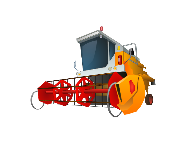
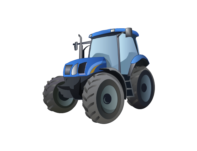
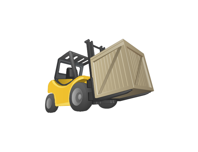
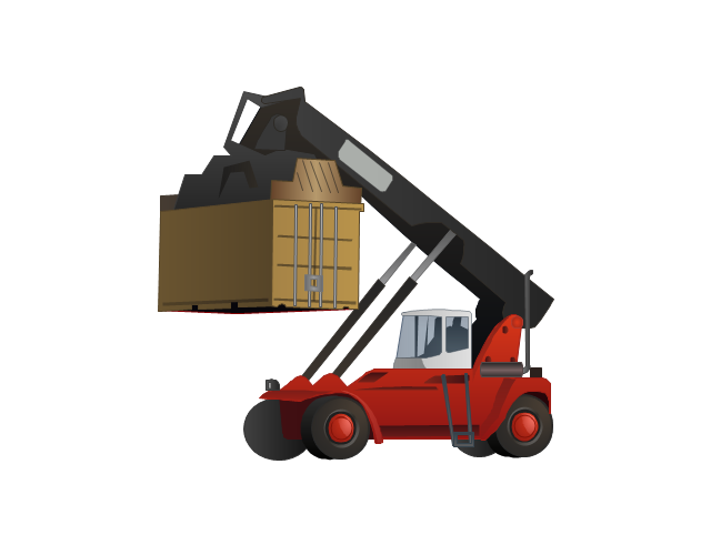
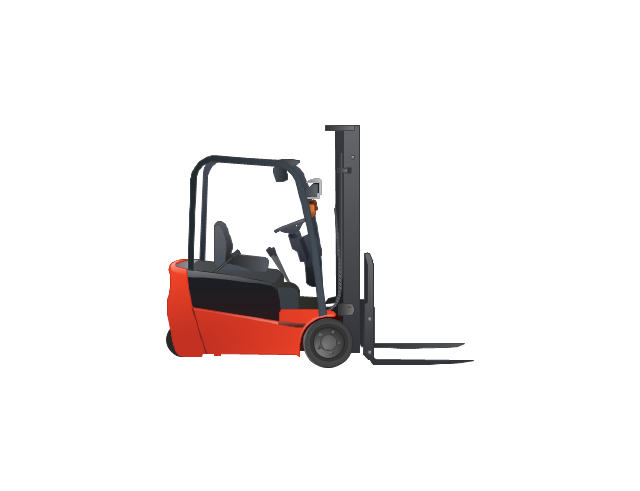
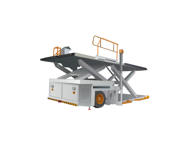
The vector stencils library "Industrial transport" contains 11 clip art images for creating heavy-duty vehicles illustrations, presentation slides, infographics and webpages using the ConceptDraw PRO diagramming and vector drawing software.
"Heavy equipment refers to heavy-duty vehicles, specially designed for executing construction tasks, most frequently ones involving earthwork operations. They are also known as, heavy machines, heavy trucks, construction equipment, engineering equipment, heavy vehicles, or heavy hydraulics. They usually comprise five equipment systems: implement, traction, structure, power train, control and information. Heavy equipment functions through the mechanical advantage of a simple machine, the ratio between input force applied and force exerted is multiplied. Currently most equipment use hydraulic drives as a primary source of motion." [Heavy equipment. Wikipedia]
The vector stencils library "Industrial transport" is included in the Aerospace and Transport solution from the Illustrations area of ConceptDraw Solution Park.
www.conceptdraw.com/ solution-park/ illustrations-aerospace-transport
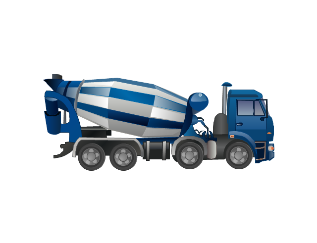
Dump truck

Concrete mixer
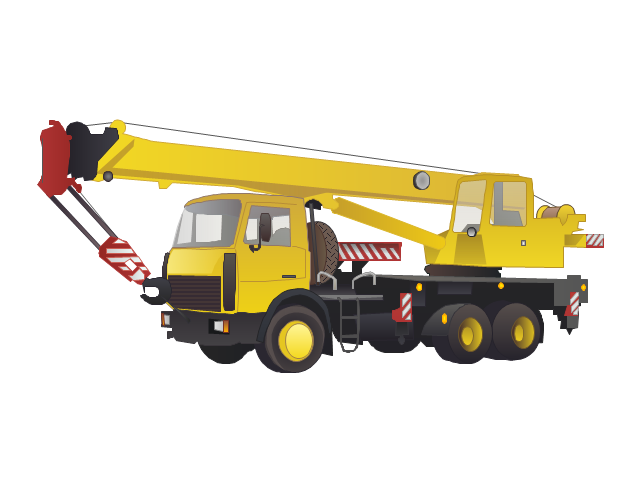
Truck crane
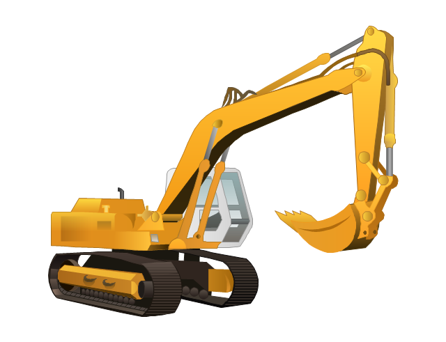
Excavator
Bulldozer
Grain harvester combine
Tractor
Forklift truck
Reach stacker
Forklift truck
Container loader
The vector stencils library "Valves" contains 91 symbols of valves. Use it for drawing plumbing and piping plans, schematic diagrams and blueprints of industrial piping systems; process, vacuum, and fluids piping; hydraulics piping; air and gas piping; materials distribution; and liquid transfer systems in the ConceptDraw PRO diagramming and vector drawing software extended with the Plumbing and Piping Plans solution from the Building Plans area of ConceptDraw Solution Park.
In-line valve

3-way valve

4-way valve

Screw-down valve

Lock-shield valve

Reel valve

Relief valve

Relief valve 2

Relief valve 3

Relief valve 4

Angle valve

Angle valve 2

Angle valve 3

Angle valve 4

Check valve

Check valve 2

Screwdown valve

Float operated valve

Float operated valve 2

Flanged valve

Flanged valve 2

Butterfly valve

Butterfly valve 2

Globe valve

Globe valve 2

Globe valve 3

Needle valve

Needle valve 2

Needle valve 3

Needle valve 4

Diaphragm valve

Diaphragm valve 2

Diaphragm valve 3

Wedge gate valve

Parallel side valve

Gate valve

Ball valve

Ball valve 2

Ball valve 3

Powered control valve

Powered control valve 2

Powered control valve 3

Relief angle valve, pressure

Relief angle valve, vacuum

Reducing valve

Reducing valve 2

Plug valve

Plug valve 2

Plug valve, straight through

3-way plug valve

Plug valve, T-port

Plug valve, L-port

3-way plug valve

3-way plug valve 2

3-way plug valve 3

3-way plug valve, T-port

3-way plug valve, L-port

Mixing valve

Characterized port valve

Manual isolation

Power signal

Statically loaded

Spring loaded

Spring loaded 2

Remote control

Diaphragm

Diaphragm, positioner

Chain operated

Gear operated

Solenoid

Weight loaded

Weight loaded 2

Weight loaded 3

Float operated

Float operated 2

Dash-pot

Dash-pot 2

Piston

Quick opening

Quick opening 2

Quick closing

Quick closing 2

Connecting unit

Connecting unit 2

Connecting unit 3

Motor element

Motor element, opens on failure

Motor element, closes on failure

Motor element, retains position on fail

Motor element, safe direction

Regulating

The vector stencils library "HVAC control equipment" contains 48 HVAC symbols. Use it for drawing HVAC systems diagrams, heating, ventilation, air conditioning, refrigeration, automated building control, and environmental control design building plans and equipment layouts. The symbols example "HVAC control equipment - Vector stencils library" was created using the ConceptDraw PRO diagramming and vector drawing software extended with the HVAC Plans solution from the Building Plans area of ConceptDraw Solution Park.
Duct, sgl line

Duct, dbl line

Return duct, sgl line

Return duct, dbl line

Supply duct, sgl line

Supply duct, dbl line

Return duct 2, sgl line

Return duct 2, dbl line

Supply duct extension, sgl line

Supply duct extension, dbl line

Return duct extension, sgl line

Return duct extension, dbl line

2-fan section, sgl line

2-fan section, dbl line

3-fan section, sgl line

3-fan section, dbl line

4-fan section, sgl line

4-fan section, dbl line

VAV box

DD-VAV box

Fan coil housing

Unit heater

Centrifugal fan

Propeller fan

Vane axial fan

Damper

Filter

Air flow station

Humidifier

Htg/clg coil

Valve

Water flow meter

Pump


Cooling tower

Converter

Heat exchanger

Boiler

Equipment

Starter

VSD

Side to bottom pipe

Side to bottom pipe, arrow
Side to side pipe

Side to side pipe, arrow
Top to bottom pipe

Top to bottom pipe, arrow
Pipe flow arrow
- Hydraulic Power Pack On Cylinder Circuit Diagram
- Diagram Of Hydrauic Circuit
- How To Draw Hydraulics Circuit Diagrams
- Hydraulic circuits | Apparatus for testing the strength of a hydraulic ...
- Hydraulic circuits | Hydraulic 4-ported 3-position valve template ...
- Fluid Power Circuits
- Circuits and Logic Diagram Software | Hydraulic circuits | Design ...
- Hydraulic circuits | Draw Network Diagram based on Templates and ...
- Hydraulic circuits | Directional control valve | Fluid power equipment ...
- Hydraulic schematic | Hydraulic circuits | Hydraulic 5-ported 3 ...
- Fluid Power Circuit Use Schematic Drawing To
- Design elements - Power sources | Energy resources diagram ...
- Hydraulic circuits | Mechanical Drawing Symbols | Mechanical ...
- Hydraulic schematic | Hydraulic circuits | Mechanical Engineering ...
- Design elements - Power sources | Manufacturing and Maintenance ...
- Technical Drawing Software | Hydraulic circuits | Mechanical ...
- Resources and energy - Vector stencils library | Design elements ...
- Energy Pyramid Diagram | Electrical Symbols — Power Sources ...
- Mechanical Drawing Symbols | Technical Drawing Software ...
- Directional control valve | Hydraulic circuits | Technical Drawing ...